Division P’s Initial AEV Sketches
Sketch 1

Weight distribution and balance were the main concerns with this design. Every part is carefully balanced to create a center of mass near the middle of the base of the platform. Two propellers balancing each other out on the sides of the center with the motor on the back to balance out the front magnet. The hope with this design is that there would be less wasted energy rocking from instability causing additional friction as well as lowering the risk of the AEV going off the rails.
Sketch 2

The main focus for this design was to create a frame that would reduce the drag force acting against the object as it moved forward. The curved front would allow the AEV to move through the air at a faster rate, and the design is relatively thin to maintain a low amount of material to keep costs low. The propellers are also located in the back of the vehicle for more forward thrust, so the program would need to be coded as a reverse movement for the front of the car to progress down the track. The battery is located in the center of the AEV base to balance the shifted weight brought on by the wheels being on the left side of the extension arm, and this battery is far enough away from the motors and Arduino to maintain a high level of safety.
Sketch 3
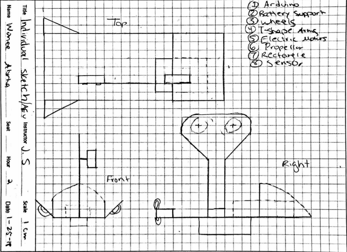
The laws of aerodynamics and forces of flight are incorporated into the design sketch. Propellers are located in the front of the AEV design to create necessary thrust. One propeller will be located on the front right and another on the front left to offset drag. The airfoil shape wings located on the left and right side of AEV creates lift when air pressure below the wing is greater than the air pressure above. The design above is weight conscious; the battery is located under the main board to allow for centered mass.
Sketch 4
Instead of using propeller pushing air, this design use a wheel contacting track to provide moving force. Theoretically this will give the better energy efficiency as all the kinetic energy from the motor is transferred into motion moving forward, comparing to propeller design which will waste lots of energy in air friction. And since the motor is directly attached to the track, this design is potentially give the best maneuverability and acceleration.
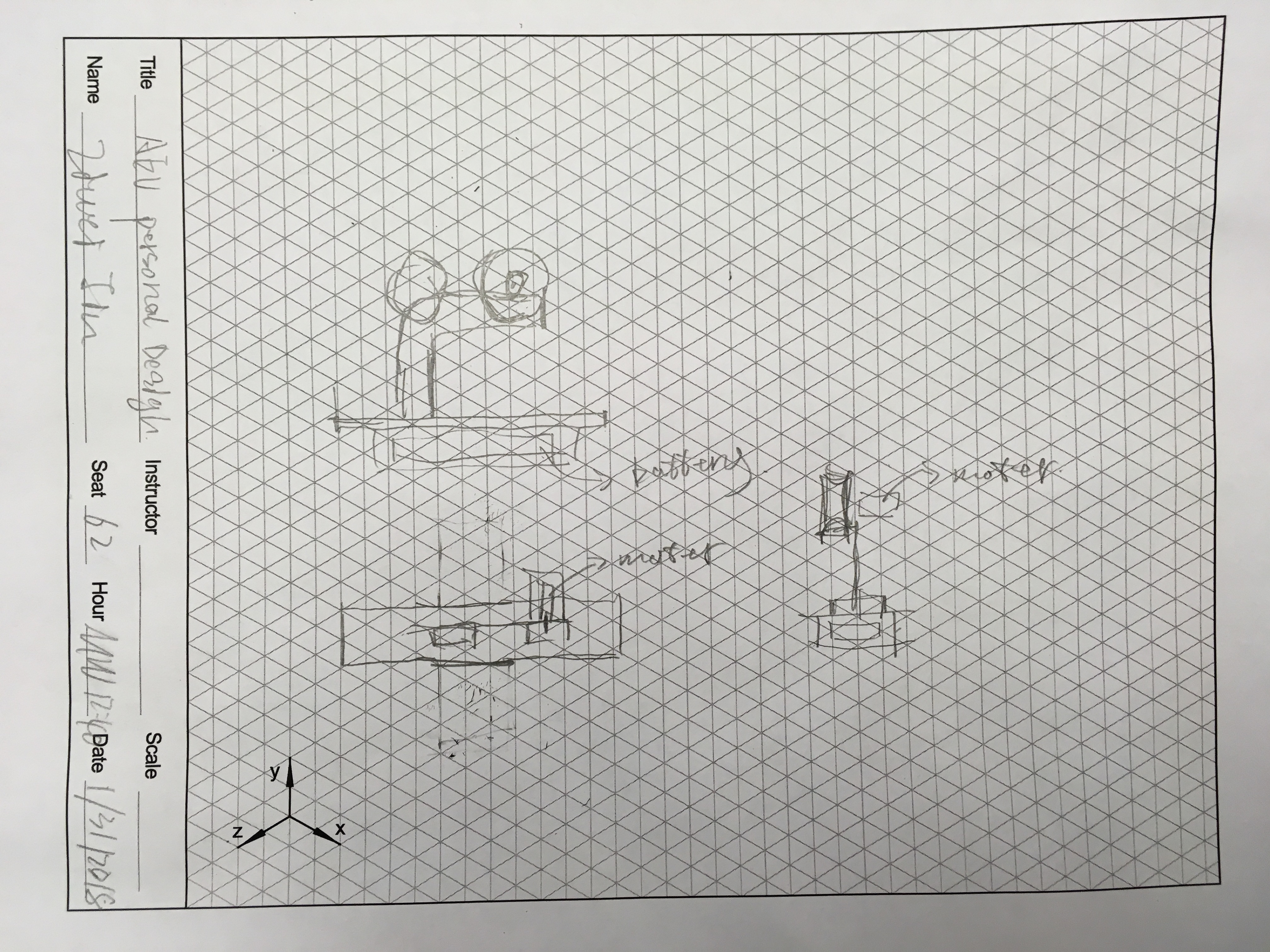
Final Sketch

Our final AEV design was based around the concept of material and energy conservation. The design is incredibly minimalistic to keep the weight of the vehicle down and so the power from the motors would be more effective in accelerating the vehicle. During our preliminary research and development, we noticed that the motors have a delay and take a few seconds to bring the AEV up to the desired speed. Therefore, cutting down the mass has allowed the device to reach the programmed speed at a quicker rate, which in turn reduces the energy needed to power the device. The research labs also indicated that the speeds the AEV will reach will not cause drag to be an influential force against the object’s motion, and therefore the group decided to remove the material that would be used to cut through air at high speeds. The motors were also placed on the side of the vehicle to assist in centering the mass of the object and so that the energy needed for the object to switch into reverse is quick and central. The battery is stored underneath the AEV to balance the vehicle on the track and to avoid close contact with both the Arduino and the motors. Finally, the magnet will be placed directly in the front center of the vehicle so that the added weight will be balanced on the rail as the AEV returns to the starting point with the new load.
AEV Sensors Discussion
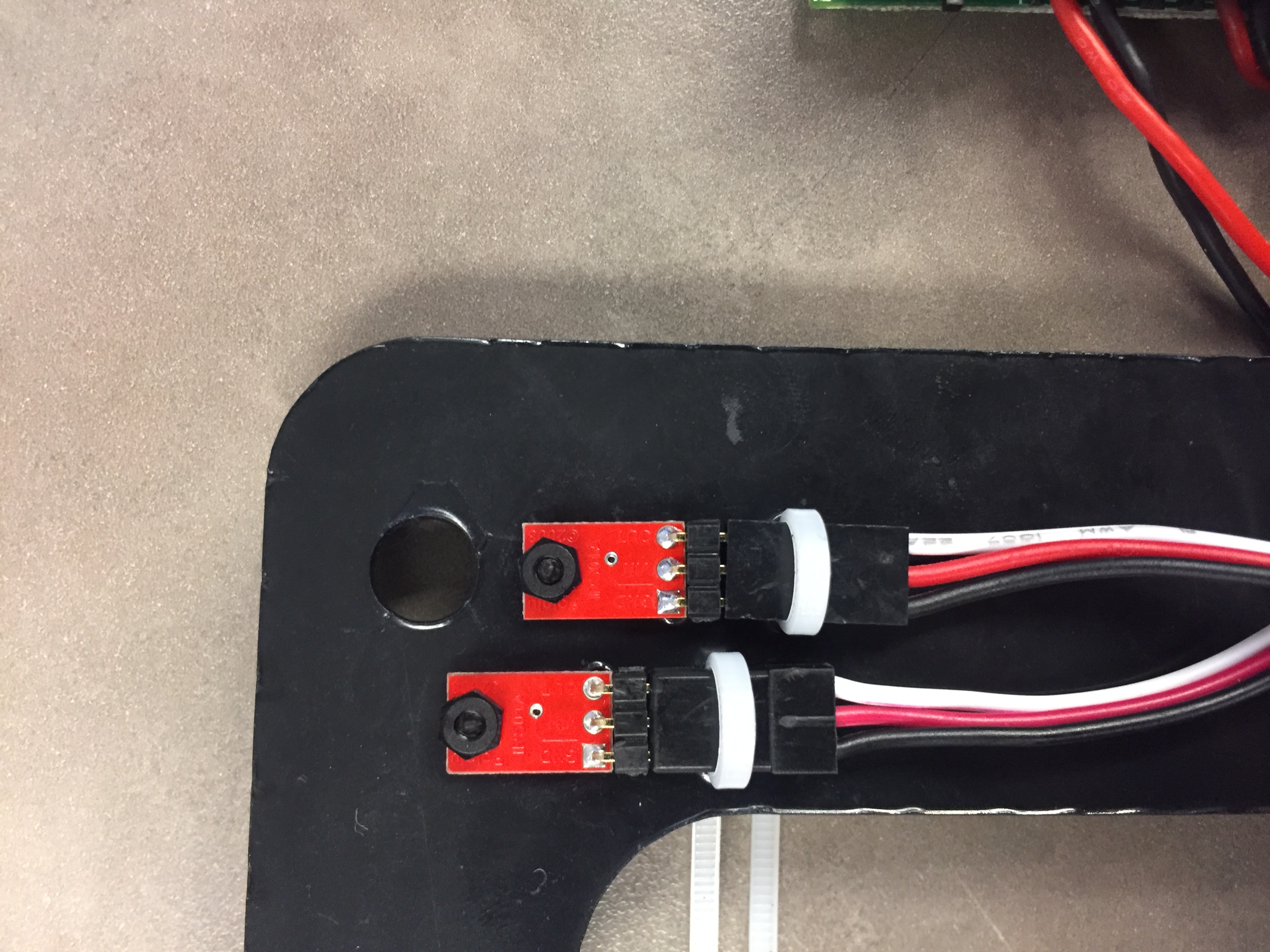
Sensors secured onto the AEV
The obstruction of the reflectance sensors by non-reflective objects are sensed due by the photosistor and LED within the sensors. These sensors are vital as it indicates position on the track and records marks (0.4875 in) based on the wheel’s revolution. The information is transferred to the Arduino, where it can now track distance and motion activity. As programmers, this type of information is important in completing the MCR; the efficiency and accuracy of the sensors is critical to constructing the code and design for the AEV.
Wheel adaptation
After enough experiment on propellor, the team started moving on to the wheel design. Team member Ziwei made prototype in SolidWork for 3D printing. The most important part was the arm designed to adapt the wheel on it, was made three parts: The arm, the motor adaptor, and the wheel.
Video. The motor fitting arm
Figure. The Wheel Assembly 

Test run video. It was a instant success, the team doesn’t need to make any modification other the altering the code for consistency and accuracy.