Tips for Working Volunteers into Your Maple Woods

Whether you have children eager to help or new volunteers wanting to participate in your woods, you are undoubtedly familiar with the tug-of-war.  On one side, you want to get new hands engaged and interested.  On the other hand, if you want something to be done right the first time, do it yourself!  At the Ohio State Mansfield sugarbush, I am constantly balancing the need to get volunteers into the woods while still maintaining standards of quality and efficiency.  Here are a few tips that we use to make sure our volunteers are a help and not a hinderance.  Hopefully you can use one or more of these ideas to streamline your own efforts to reach this delicate balance.

Precision tappers are expensive, but precision tappers are also efficient and effective at controlling the single most important activity in your woods – tapping!  Precision tappers allow you to set the exact tapping depth and reliably expect that the grip points on the end of the device will result in a steady straight taphole each and every time.  While they are costly, our taphole consistently went through the roof when we employed these this sap season for the first time ever.  Precision tappers are probably not for the average producer, but if education and outreach is a central part of your mission, they may well be worth the cost.

An extra step for ensuring excellent tapping is to clearly mark your tapholes at season’s end with a dot of forestry paint.  If you are employing geometric tapping (e.g, over 3 inches-up 6 inches, over 3 inches-down 6 inches, …), then next year’s instructions simply become “find the [insert color of your choice] dot, space over, and tap.”

While we are on the subject of tapping, choose a sacrificial tree to train your tapping crew.  This double-trunked specimen is below our sap shed, has half its crown busted out, and has been tapped no fewer than 100 times in the past 5 years.  Our sacrificial tree is a classic “take one for the team” scenario.  Drilling a good taphole is only part of proper tapping.  How to properly set the spout is just as important, and in my experience, more apt for abuse and mistakes.  Repetition with back-and-forth feedback are minutes worth their weight in gold if volunteers or new help tap a significant portion of your woods.  Make your mistakes here – not on your production trees.

Lead by example in the sanitation department.  If your sap tank is filthy and scummed over, it’s hard to expect your help to take you seriously about sanitation in the rest of the woods.  If your tapping gear is mud-caked and filthy, it’s probably a bit hypocritical to expect your volunteer crew to keep your gear spotless and spit-shined.  Be diligent about sanitation, speak often about sanitation, and your help will take sanitation seriously as well.

Keep a volunteer’s job simple but always give them a roll of flagging tape to pinpoint potential issues they may run across.  If they see something suspect, have them tie up some flagging tape so you can check it out later.  Better yet, and particularly useful for keeping track of progress and directions in the woods, if you incorporate some numbering system into your main lines and laterals.  Below you’ll see an aluminum write-on tag that we tie on each lateral loop starting with main line number and ending with lateral line number.  So in this case, you’re looking at the 3rd lateral line on main line #1.  Navigation and giving directions becomes exponentially easier with this numbering system in place.

While we are talking about lateral loops, show your volunteers the rapid visual checks a producer has to ensure their woods are working properly.  As volunteers walk the woods, it’s easy to visually confirm that sap is traveling around the loops signaling a functioning system.  The same goes for sap flow through the drops into the laterals.  If the loops or drops are empty but the rest of the woods is running good, a strip of flagging tape might be warranted.

And lastly, do not realistically expect perfection.  I found this double spout tree untapped just last week.  It’s too bad we didn’t get this one tapped earlier, but if 1 big tree’s production is the price I pay to get someone excited about maple – that’s a price I suppose I’m willing to pay.

Fall Maple Assessment – Get Ready for Next Season

The leaves have changed and have mostly fallen from the trees.  In some corners of Ohio, the first snow has already fallen.  For maple syrup producers, that means the push to get ready for a new season is upon us.  This is the best time of year to walk through your entire operation and systematically appraise your operation.  Now is the time to walk your sugarbush with a notebook in hand.  This assessment process allows you to locate the little things that make a big difference when the sap starts flowing.

Begin by looking at the most logical place first – your trees!  What condition are the trees in?  Are they healthy?  Did the June storms cause wind damage to the crowns?  The health of the trees will determine the number of taps per tree, and to some extent, the depth of your taphole.  If trees appear stressed, consider tapping a bit shallower (1.5 inches) rather than the full 1.75” or 2” depth.  It is not unusual to rest a tree for a season, allowing it to overcome obvious stressors.

Now reflect on your tubing system’s performance the very first year it was installed.   Compare that year to the way your system performed last year.  Have you noticed a drop-off in performance? It is easy to blame a poor season on the weather; in reality, the cause could be the age of your system and some neglected repairs.  For many producers, the first inclination is run out into the woods looking for squirrel chews and start repairing lines.  Do not get me wrong, that is important, but it is just one stage of a more holistic leak detection process.  The first order of business should be to inspect the lines for more systemic degradation and disrepair.  I hope that everyone is starting every season with all new spouts?!  However, your assessment should look deeper still.

When was the last time you changed the drops?  How long are the drops?  Are they long enough to allow you to reach around the tree?  Thirty-two inches is a good starting point for drop length in established systems.  What condition are your tees in?  Bad tees lead to micro leaks that sometimes are worse than squirrel chews because they are harder to locate and might be ignored an entire season.  What condition are your laterals?  Do they need to be replaced?  Are you noticing a mold buildup in the lines?  Are your lines patched together because of multiple repairs and damage?  When you replace laterals, it is a good time to look at the overall layout of the lateral system?  Count your taps on each lateral to determine if one is overloaded.  Remember, any given lateral should only be carrying 5 to 7 taps.  Also look at the slope of each lateral.  Is it running straight and tight and downhill for best performance?  What about your saddles, are they leaking?  Old saddles, just like old tees, need to be replaced on a regular basis – at least every 5 years.  Old saddles are often one of the major causes of leakage in maple tubing systems.

The next area of concern is the mainlines.  Ultraviolet light and wind damage are major causes of stress on mainlines.  Mainlines are good for 10 to 15 years, but eventually they must be replaced.  Yes, that is an expensive project!  However, the benefits outweigh the cost.  Installing new lines also allows you to remove damaged and unwanted trees during the repair.  Sugarbush stand improvement is important as it will improve the overall health and productivity of your sugarbush in the long-term.  Hazard trees, such as standing dead ash, should also be dealt with during a mainline replacement project.

It is easy to see how performing a pre-season assessment of your tubing system can be beneficial.  And that is just the tubing system!  After you walk your sugarbush – clipboard in hand – go back to the sugarhouse and develop an improvement plan. What must you buy?  In what quantity?  When will it arrive?  Are their supply chain delays?  Rank everything you have found in order of importance and start chipping away at your list – sap season will be here before you know it!

Optimizing the Performance of My Vacuum Tubing System, Part III

The goal of the previous two articles (Part I, Part II) and this final installment is for you to realize that there are many factors that go into installing and running a maple vacuum tubing system. All the factors are interrelated and each one needs to be careful considered on the part of the operator.  The below information is contained in the Cornell New York State Tubing and Vacuum System Notebook (NSTVN) written by Cornell University’s Maple Specialist Steve Childs.  Much of the information is these three posts is a synthesis of past content with some more recent best practice guidance.

Part I introduced basic concepts of vacuum in a tubing system, some different variants within vacuum systems, and the different factors (most well within the control of the producer!) that influence vacuum levels throughout a system.  Part II walked you through how to calculate vacuum levels within your system and how to ensure your production needs are met by your system’s capacity.  The final installment will help direct you towards a vacuum pump that will do the job you need it to do.


When someone brings up the subject of vacuum, one of the first questions producers ask is, “What size vacuum pump will I need to run my system?” They will also sometimes ask, “Will the old rotary vane pump my grandfather abandoned in the barn 10 years ago (or longer…) do the job?” The question I also ask back is this, “What vacuum level do you want to run at today and into the future?”

We should get the second question out of the way first. Grandpa’s pump was designed to milk cows, and Bessy would get a little fussy if the vacuum level were to jump above 15 Hg. So the simple answer is that Grandpa’s pump will work, but it is not designed for optimizing maple production. But if you are happy with a modest increase in production beyond simple gravity-fed lines, dust off the old rotary vane pump and run it at the recommended RPM. Moving on to where the maple industry has evolved.

To review, vacuum pumps are designed to remove air from the system, and we already know that vacuum pumps are rated in terms of their ability to remove cubic feet per minute (CFM) from the system. Two additional factors come into play when comparing vacuum pumps. One is the horsepower rating, or the power required to remove air at high levels of vacuum. As the air is removed from an enclosed area the molecules of air in that area become very sparse. A pump must work very hard to remove the remaining molecules of air in the system. The pump must also overcome the force of the negative pressure inside that enclosed area, and this challenge requires more horsepower. A larger pump with a higher CFM rating has a higher capacity to accomplish this task but bigger pumps also require higher horsepower motors. The final factor is pump speed. If you turn a pump faster your will move more air thereby increasing the pump’s capacity. However, over-speeding a pump can cause excessive wear on the pump. This becomes a critical factor when sizing a gasoline of diesel motor driven pump. Pullies need to be sized correctly or performance is sacrificed.

Caption: Vacuum gauge measuring 26+ inches of vacuum

Most of today’s liquid ring, flood vacuum, rotary claw and new age rotary vane pumps are designed to run at vacuum levels up to 29 inches. An important thing to remember is that all pump ratings and vacuum level capacities are preformed using a standard test at the factory removing air from a sealed vessel and a performance curve is developed. This is done in a controlled environment. Now the question becomes what happens when you lower the air temperature and increase or decrease the barometric pressure? The result is confusion. Today, many maple equipment companies are simply listing pump sizes by motor horsepower instead of by CFM capacity. I have personally never seen optimum conditions out in a sugarbush in February and March, and as pointed out above, motor horsepower is only one factor determining pump capacity.

Another question I have is this – “What is the likelihood of that pump reaching 29 inches of vacuum in your sugarbush?” How many times have you heard producers tell you that the pump gauge mounted somewhere near the inlet of the pump is reading 28 inches of vacuum and therefore he must be producing 28 inches of vacuum at every tap in his woods? The harsh reality is that out in the woods he might be struggling to produce 15-20 inches of vacuum. What has the producer not factored in? First, line loss because line diameter can be restricting flow and impairing the ability of the vacuum pump to remove all the air from the system. Second, the producer might have an abundance of leaks in his or her system. The reality is that the only vacuum reading that counts is the reading that is taken out in the woods at the last tap. Today in the age of maple tubing system monitors, producers can know exactly what level of vacuum they have at the end of each line. They can also monitor the level of vacuum at the releaser and make the comparison to the end of their lines and isolate and correct problems as they occur.

To determine what sized pump your operation requires, you should begin by constructing an evaluation like the one used in the NY State Maple Tubing and Vacuum System Notebook. Start by calculating the proper line size for the number of taps you have now and do not forget to think ahead regarding possible expansions you may make in the future. Factor in your equipment such as the releaser you want to run, whether you have lifts in your system and other CFM consuming features. Do not forget to build in some reserve performance to allow for possible leaks and for keeping up with your during peak runs. At this point, you should have a good idea of the right-sized pump for your operation. If you are right on the edge of meeting CFM demand, you should strongly consider buying a pump one size or even two sizes bigger than you planned especially if expansion is in your future. What’s the old adage? Buy once, cry once.

The Bottom Line

You have now made all the calculations and are beginning to understand the logic and principles behind setting up a vacuum tubing system. So what is the return on investment (ROI) for spending money on a bigger pump and increasing the size of your lines? For that answer, let’s look at yield research done at UVM Proctor Research Center. For the UVM study, the goal was to determine yields in systems up to 25 inches of vacuum. The results showed that sap yield doubles when vacuum is taken from 0 to 15 inches (8 gallons per tap). From 15 to 20 inches, the payoff was a 3 gallon increase, and pushing vacuum another 5 inches to 25 Hg resulted in an additional 2.5 gallons. At 25 inches vacuum, you have added nearly 14 gallons of sap per tap.  Even at 20 inches of vacuum, the additional yield is still over 10 gallons. In today’s market you can add a modern vacuum pump, a releaser, and moisture trap for less that $10,000. If you increased your production by 75% on 1000 taps, you would go from 250 gallons a year to 400. If those 150 extra gallons sold on the retail market for $50.00, your return would be $7,500 dollars. At that rate, you have paid for your vacuum upgrade in two years. What are you waiting for?!

This is the final installment in the 3-part series dedicated to optimizing your vacuum tubing system.  Be sure to leave questions or comment below.

Author: Les Ober, Geauga County OSU Extension

Optimizing the Performance of My Vacuum Tubing System, Part II

The goal of the previous article (Part I), this article, and the next is for you to realize that there are many factors that go into installing and running a maple vacuum tubing system. All the factors are interrelated and each one needs to be careful considered on the part of the operator.  The below information is contained in the Cornell New York State Tubing and Vacuum System Notebook (NSTVN) written by Cornell University’s Maple Specialist Steve Childs.  Much of the information is these three posts is a synthesis of past content with some more recent best practice guidance.

Part I introduced basic concepts of vacuum in a tubing system, some different variants within vacuum systems, and the different factors (most well within the control of the producer!) that influence vacuum levels throughout a system.  Part II will walk you through how to calculate vacuum levels within your system and how to ensure your production needs are met by your system’s capacity.

It is not uncommon during a peak or flood run for your vacuum to drop. If you maintain your lines and are running a tight, leak free system what is the possible explanation for this sudden drop in vacuum? One possible reason is CFM Allocation (air flow measured in Cubic Feet per Minute). In the most basic systems, all vacuum lines are properly and equally sized with the same number of taps per line and all running to a single collection point. The CFM requirements to maintain optimum vacuum will be equally distributed across the whole system. For example, if you have 4 lines of equal diameter connected to a 60 CFM vacuum pump each line would receive 25% of the vacuum CFM (15 CFM). According to theory that would be enough vacuum to run 1500 taps on each line. To use another example, if you are using a 20 CFM pump on a system with 4 equally sized lines and each line serviced 200 taps each for a total of 800, then you would be allocating slightly less than 5 CFM to each line – still more than enough to run each line. However, Total CFM utilization is not always dictated by the number of taps in the woods. One must account for the CFMs utilized by other components of the system, such as if you run a mechanical releaser and other add-on features like lifts or reverse-slope releasers. This reduces the number of available CFMs to accommodate tree loss and leak loss.

Caption: Vacuum Pump with Vacuum Gauge

Now let’s add some complexity to our scenario. Let’s say you expand your 800 tap operation by adding 600 taps to the backside of one of your 200 tap lines. What happens to your 20 available CFMs if you remove a 1” line and replace it with a 1 ¼” line to service the line that now has 800 taps. Now you have 3, 1” lines and the new 1 ¼” line servicing 1400 total taps.  Now you must calculate your line allocation to determine proper CFM distribution.

The first step is to calculate the cross-sectional area of each pipe which is easily accomplished with basic geometry’s “area of a circle” equation.

Cross-sectional Area of a Pipe
Diameter Area
¾” 0.44 in2
1” 0.78 in2
1 ¼” 1.23 in2
1 ½” 1.77 in2
2” 3.14 in2
3” 7.07 in2

Second, you need to determine the percentage of your total vacuum going to each line.  As a reminder, our example has 4 mainlines: 3, 1” lines and a single 1 ¼” line.  Here is a simple way to determine vacuum distribution.

The cumulative cross-sectional area of our 3, 1” lines = 0.78 + 0.78 + 0.78 = 2.34 square inches.  And for the single 1 ¼” line, 1.23 square inches.  The grand total sums to 3.57 in2.

Now divide the cross-sectional area of each line by the total to see what proportion or percentage of vacuum is being applied to each line.  You will find that each 1” line is pulling 22% of your overall CFMs which leaves 34% of the vacuum for the 1 ¼” line.  By CFMs (remember you started with 20 CFMs), each 1” mainline is pulling a maximum of 4.4 CFM and the single larger line is hovering just under 7.

You can quickly see that you are sending way too many CFMs to each of the 1” lines and not enough to maintain good vacuum on the 1 ¼” line.  A quick solution would be to combine the 3, 1” lines into a 1 ¼” manifold with the existing 1 ¼” line going directly into the releaser. That would result in the releaser with just two lines coming out each equally sized at 1 ¼”. This solution would re-allocate 50% of the CFMs to each line solving the problem of line allocation.

It is important to remember, you need to account for leaks that will introduce more air into lines. You might be able to maintain peak vacuum on most average days, but will your system  keep up with sap flow when the big run hits and you need to move as much air as fast as possible to maintain vacuum levels. If you have your lines sized properly, you now need to take the next step to determine what size pump you should purchase.

Stay tuned for Part III (What Pump to Purchase?) on Thursday and be sure to leave questions or comments!

Author: Les Ober, Geauga County OSU Extension

Optimizing the Performance of My Vacuum Tubing System: Part I

The goal of these next 3 articles is for you to realize that there are many factors that go into installing and running a maple vacuum tubing system. All the factors are interrelated and each one needs to be careful considered on the part of the operator.  The below information is contained in the Cornell New York State Tubing and Vacuum System Notebook (NSTVN) written by Cornell University’s Maple Specialist Steve Childs.  Much of the information is this and the next two posts is a synthesis of past content with some more recent best practice guidance.

When we talk about tubing systems, we have two roads to travel. One is a gravity system and the other is a vacuum system. A conventional 5/16” gravity system is not much different from running sap into a bucket. The yield is much the same as collecting sap in a bucket. When we add vacuum to a tubing system, we increase the sap yield 5% for every inch of vacuum we generate in our system. For example, if we produce 15 inches of vacuum in a line, we should be able to almost double our sap yield.  The first year after installation is always the best. As time on a system accumulates, wear-and-tear hampers performance.

Caption: Year 1 Production with a Brand-New System Should Provide Your Best Vacuum Levels

The definition of vacuum is the absence of air. The maximum level of vacuum achievable on any given day is determined by the barometric pressure. This means that our vacuum level can never exceed the barometric pressure in the location of our sugar bush. There are two way to measure vacuum pump performance, Inches of Mercury (hg) and Cubic Feet per Minute (CFM). Inches of mercury measures the negative pressure produced when air leaves the line. For example, if 50% of the air is removed then the inches of mercury should be somewhere between 14 and 15. At 25 inches of mercury, approximately 85% of the air has been removed from the lines. CFM on the other hand measures the amount of air being evacuated from the lines in units of cubic feet per minute. This is the amount of air that a vacuum pump is pulling out of the system in one minute’s time. Where is the air coming from? The answer is gas that is forming inside the tree and being expelled through the tap hole. As a rule of thumb, there is a 1 CFM requirement for every 100 taps on the line.  However, the biggest contributors are leaks allowing air to enter the system through damaged or aging tubing. This statement emphasizes the importance of managing leaks in a vacuum tubing system.

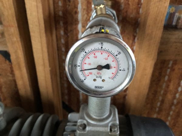
Caption: Vacuum Gauge Measuring Vacuum in Inches of Mercury (hg)

Speaking of leaks, the most important part of operating any maple syrup system is the time you spend in the woods making sure your vacuum tubing system is leak-free. Much of the rest of the article is spent discussing different technologies and equipment, but the simple fact of the matter is this – the best equipment with poor care in the woods won’t do you a lick of good when it comes to putting more maple syrup on tables of your customers. You must always account for leaks that introduce air into lines. You might be able to maintain peak vacuum on average days, but your system will show its weak points when sap flows are running fast and you need to move as much as air as fast as possible to maintain vacuum levels. Being able to spot and repair leaks quickly is essential. To accomplish this, you should design your system so you can isolate lines to pinpoint problems. This can be done by compartmentalizing your system with valves and vacuum gauges placed at the starting point of each line. The installation of a tubing monitoring system can be a wise investment as well, and the time saved and extra sap produced will pay for the cost of the upgrades in short order.

Back to our lesson on vacuum and barometric pressure. There are factors that have a direct effect on barometric pressure. One is altitude. As the altitude increases the maximum barometric pressure declines (rule of thumb: for every 1000 feet of elevation you lose 1 inch of vacuum). For example, at sea level, or 0 altitude, the average barometric press can be 29 inches; at 2000 feet, the average maximum barometric pressure obtainable is only around 28 inches. In addition, barometric pressure changes under different environmental conditions, and variations in barometric pressure caused by atmospheric changes can occur multiple times in a day. If we are running a vacuum pump under a low barometer at 2000 feet elevation, we might struggle to maintain 28 or even 27 inches of vacuum on a very tight well-maintained tubing system.

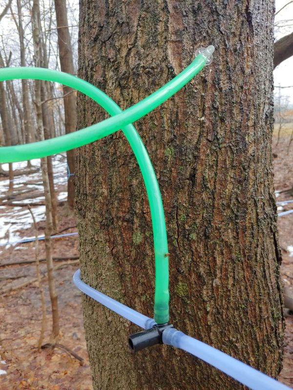
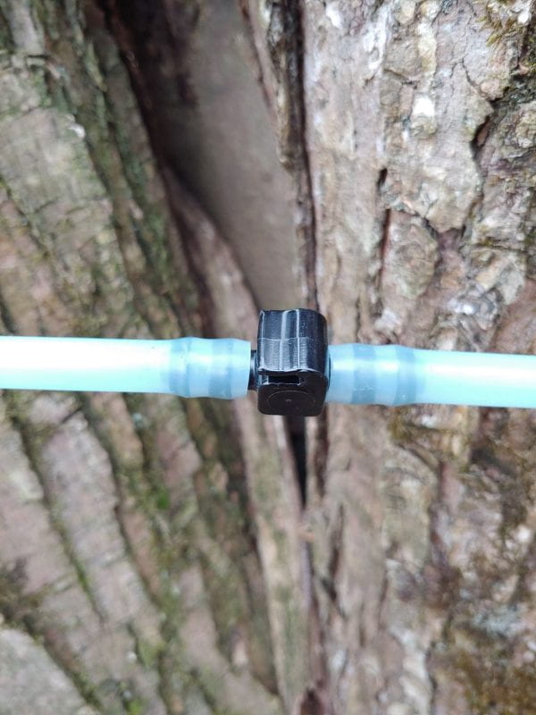
Sap moves down the line by gravity on a system of tubes suspended with wire. The basic components are spouts, tees, and drops moving sap from the tree into lateral lines. A lateral line should have no more than 5 to 10 taps per line and should be no longer than 100 feet in length. The lateral lines flow into main lines. In large systems, secondary mains flow into Wet-Dry lines and or trunk lines (large diameter lines) that move the sap to a central collection point.   To properly function, sap lines should be straight, pulled tight, and sloped downhill. To this point gravity systems and vacuum systems are similar, with the gravity system relying on slope and Newton’s law of gravity to move the sap.

Caption: 65 CFM Bush R-5 Vacuum Pump

When vacuum is added to the system, sap flow is aided by the movement of air.  The components of a vacuum tubing system are the vacuum pump, which is connected to lines via a sap releaser. Even though it is called a vacuum pump, it is not a pump in the conventional sense of the word and that is a bit confusing. A conventional pump moves liquid creating pressure ahead of the liquid and suction on the backside of the liquid. There are other types of pumps used in maple production. For example, a diaphragm pump is a conventional pump and that creates enough suction (secondary vacuum) to draw sap from a tree. However, if liquid is not present in the lines that suction can be lost.  A true vacuum pump moves air, not liquid and it creates a higher level of vacuum (absence of air) as the air is removed from the lines. That level of vacuum can be maintained with or without sap in the lines and will only drop if a leak allows outside air to enter the line.  Because the pump is designed to move only air, the liquid must be separated from the pump. This separation process is performed by a sap releaser. If sap enters the vacuum pump severe damage to the pump can occur! To prevent this from happening, a moisture trap is placed between the pump and the releaser.

Caption: Sap house releaser (right) with Vacuum Piston Pump (left)

A properly sized vacuum pump with a proper CFM rating will be capable of removing air faster than it is introduced. However, there is one factor that can interrupt and slow that process – line size. Vacuum lines are designed to conduct air to the pump. If your line diameter is too small, the air movement will be restricted requiring more time for the pump to clear air from the lines. This phenomenon is referred to as line loss. The smaller the line the more the air flow is restricted resulting in higher line loss. As an example, a 60 CFM pump set at 15 inches of vacuum hooked to a 3“ line can maintain over 40 CFM out to 5000 feet. However, that same pump hooked to a ¾” inch line is incapable of delivering 15 inches of vacuum at 2500 feet from the pump. Line loss increases the time (recovery time) needed to evacuate air from the line and restore peak vacuum level.

What is missing from this equation? The capacity of the line to conduct liquid. Every diameter of pipe has a maximum liquid capacity. The size of the pipe that is needed is determined by the number of taps flowing into the pipe. Each tap during a peak flow might contribute upwards of 0.2 gallons of sap per hour. Once you calculate the amount of sap flowing in you can determine the size of the pipe that is needed. There is however one caveat, the steeper the slope the faster the sap moves through the line thereby effectively increasing the capacity of a given-sized line on steeper slopes. Slope can also influence sap flow in other ways. The portion of the line, 50 feet or longer with the least amount of slope, will strongly influence sap flow. Examining this critical portion of your line might dictate a necessary increase in line diameter to allow for adequate air and liquid flow. Remember, you need to move air as well as liquid through a maple pipeline. To do this you must maintain the proper ratio of air to liquid inside the line so as not to inhibit sap movement. If you look at a working cross section of tubing it should contain 60% air and 40% liquid. This is a primary consideration when determining what size of line to use in your sugarbush.  If the liquid level increases beyond that ratio or is uneven (wavy), the air movement will be restricted resulting in a drop in vacuum.

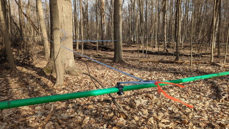
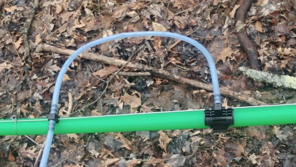
Caption: Whip Connection to a Wet-Dry Line.

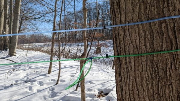
There are two ways to solve this problem. The first would be to increase the size of your main lines but 1 ½” inch and 2” tubing is expensive, and it adds to the overall expense of the tubing system. Still, increasing tubing size may be justified if you have a large number of taps coming into a trunk line. The other alternative is to install a dual-line conductor commonly known as a Wet-Dry Line. Composed of two lines of equal size (or a dry line slightly larger than the wet line), a Wet-Dry system can excel at moving sap across flat areas or areas where multiple secondary mainlines merge. Secondary mains may enter the Wet-Dry line at a booster, or a line configuration called a whip. This allows sap to move down the wet line without impeding the airflow in the dry line. This set-up is particularly useful in flat areas where slope in minimal and sap flows slowly which may inhibit the necessary amount of air flow. Wet-Dry lines can be a cost-effective way to move sap through areas of minimal slope.

Stay tuned for Part II in a couple of days and be sure to leave questions or comments!

Author: Les Ober, Geauga County OSU Extension

Vacuum Tubing Systems, An Update

This is an update for an article I wrote on the Ohio Maple Blog way back in 2013. It was entitled “Tubing or Pump: How to Optimize Your Tubing System’s Performance.” A lot of knowledge has been gained since that original article. In fact, a whole new type of gravity tubing system, 3/16″, has been introduced and has been overwhelmingly accepted by maple producers.

When we talk about tubing systems we have two roads to travel. One is a gravity system and the other is a vacuum system. A conventional 5/16″ gravity system is not much different from running sap into a bucket. It does save labor but the yield is much the same. But when we add vacuum to a tubing system, we can increase the sap yield 5 to 7% for every inch of vacuum we place on our system. For example, if we produce 15 inches of vacuum in our lines, we should be able to double our sap yield.

The definition of vacuum is the absence of air. The level of vacuum that is achievable is determined by the barometric pressure for any given day. This means that our vacuum level can never exceed the barometric pressure in the location of our sugar bush. There are factors that have a direct effect on barometric pressure. One is altitude. As the altitude increases the barometric pressure decreases. At sea level, 0 altitude, the average barometric press can be 29 inches and at 2000 feet the average barometric pressure is approximately 28 inches. In addition, barometric pressure changes under different environmental conditions. It can change multiple times during the course of a day. This is most important when we are boiling syrup because it changes the boiling point of water. But if we are running a vacuum pump under a low barometer at an altitude of  2000 feet, we might also struggle to maintain 27 to 28 inches of vacuum even on a very tight, well maintained tubing system. This statement also emphasizes the importance of managing leaks in a vacuum tubing system. Every leak adds additional air to the system making it harder for the vacuum pump to achieve and maintain high vacuum. The amount of air moved out of a system is measured in Cubic Feet per Minute (CFM). It is important to be able to differentiate between Inches of Vacuum and CFM. To successfully raise your vacuum level, you have to be able to remove the air from your tubing system. Once the air is removed, your vacuum level will increase unless you are letting air in through leaks.

Now let’s look at what happens inside a maple tubing line. A conventional vacuum pump is designed to move air not liquid.  This means that a vacuum pump is pulling air out of the system while the trees and the leaks are adding air into the system. A properly sized vacuum pump with a proper CFM rating will be capable of removing air faster that it is introduced. The only thing that will slow that process is line size. If your line diameter is to small, the air movement will be restricted requiring more time for the pump to clear the air from the lines. This is commonly referred to as line loss. The smaller the line, the higher the line loss and the longer it will take to re-establish your peak vacuum level. That is why tubing design and pump size are so important in a conventional vacuum system. It is also very important to note that in a vacuum system, liquid does not need to be present to create a high vacuum. The movement of sap is secondary. As the vacuum level builds it creates a siphon that pulls the sap along with the air. In fact, when we look at the space inside a cross section of tubing we should strive to maintain a ratio of 60% air and 40% liquid. If the liquid level increases or is uneven (wavy), then the air movement will be restricted and the inches of vacuum will drop.

Let’s look at some other alternatives to move sap through a tubing system. One of the more popular alternatives to conventional vacuum is the diaphragm pump. Let’s look at what happens with a diaphragm pump. Diaphragm pumps are water pumps that unlike vacuum pumps are designed to move liquid – not air. Because they move water and not air, their capability of creating CFM is minimal at best. Manufacturers tell us that these pumps are capable of creating 20 plus inches of vacuum. How do you create a vacuum with these pumps when their ability to move air measured in cubic feet per minute is limited? In a sugar bush, your lines are hopefully sloped toward your tank and gravity allows sap to flow toward the pump. Once the pump picks up the sap on the intake side, it then accelerates the flow in the line. The pump simultaneously pushes the sap under pressure through the outlet. Because the pump is pulling hard on the sap and pushing it through the outlet, it creates a solid column of sap. As this column of sap moves down the line, the air and liquid combines thereby creating a negative pressure on the backside of the column. This negative pressure can be measures with a vacuum gauge. This continues until the sap flow slows down. As the sap flow slows the vacuum level begins to drop. Once the flow is terminated, the pump can no longer push sap through the outlet, and the negative pressure will ultimately disappear. If you run the pump without liquid, you risk damaging the pump. The biggest thing to remember is that a $200.00 diaphragm pump will not remove air from the system by itself. It has to move liquid to create a negative pressure on the backside of a column of sap. I know the above statements will create controversy from those that are using diaphragm pumps successfully. There are ways to tweak a system to create increased vacuum during low flows but the ultimate end is reduced or no vacuum. The other thing to keep in mind, if you want to be successful with a diaphragm pump, is to keep your tubing system free of leaks. Leaks will result in poor pump performance. Also protect you pump from freezing and ice in the lines. Ice can damage diaphragms. Diaphragm pumps are a good choice in small operations where an increased level of vacuum during a good run is better than no vacuum at all. But diaphragm pumps were never intended to a replace a conventional vacuum system and they never will.

Author: Les Ober, Geauga County OSU Extension

The Quest for High Vacuum Part 2

When you bring up the subject of vacuum, one of producers’ first questions are “What size vacuum pump will I need to run my system?” They might add “Is the old rotary vane pump my granddad left in the barn good enough?” The question I ask them in return is “What vacuum level do you want to run today and into the future?”

As I stated in Part I, there are two ways to measure vacuum pump performance, inches of mercury (Hg) and CFMs (cubic feet per minute). Inches of Mercury (Hg) measure the negative pressure produced when air leaves the line. For example if 50% of the air is removed, then the inches of mercury should be 15 given the maximum pressure possible is between 29 and 30. At 25″ Hg, approximately 85% of the air has been removed from the lines. CFM measures the amount of air being evacuated from the lines measured in cubic feet per minute. Pump ratings for CFM are assigned based on their ability to remove air, and this is largely determined by the size of the pump.

Two other factors come into play when comparing vacuum pumps. One is the horsepower rating. As the air is removed from an enclosed area, the molecules of air in that air become very sparse. The pump has to work harder as the air becomes thinner. The pump also has to overcome the force of the negative pressure inside that area. This requires more horsepower. A larger CFM rating does this faster but requires more horsepower. The other factor is pump speed. If you turn a pump faster, you will move more air and will increase the capacity. However, over speeding a pump can cause excessive wear on the pump.

So to answer the second question first, Granddad’s pump is not designed to produce anything over 15 inches of vacuum and that is not high vacuum by today’s standards. Most of the liquid ring, flood vacuum rotary claw and new-era rotary vane pumps are designed to run at vacuum levels up to 29 inches. Remember all of the pump ratings and their ability to increase vacuum level are done at the factory removing air from a sealed vessel. Based on this information, a performance curve can be developed. What makes this whole process more confusing is that many maple equipment companies are now listing there pump sizes by motor horsepower instead of by CFM capacity. As pointed out earlier, motor horsepower is only one factor determining pump capacity. When questioned about CFM, one dealer told me his pump will develop 11 CFM at 29 inches of vacuum. This has to be a specification taken off of a performance curve taken at the factory. The more important question is how likely is that pump to ever reach 29″ of vacuum in a working maple system? The fairest comparison should be made when the CFM is measured on a pump being run at 15 inches of vacuum. Otherwise, without having the performance curve data in hand for every pump you are considering, how can a customer make a fair comparison – quite simply, he or she can not.

So are the dealers wrong when they tell you that your pump will produce 29 inches vacuum? The answer to that question is both yes and no. As stated, most pumps are capable and have been tested to deliver 29 inches of vacuum. This is clearly shown on the pump performance curves. However, because the performance curves are standardized to barometric pressure at sea level, an adjustment for elevation above sea level needs to be made. For every 1000 feet of elevation you lose 1 inch of vacuum, this means the highest vacuum level achievable at an altitude of 2000 feet is around 28 inches depending on the barometric reading on any given day.

So what is going on when a producer tells you that his pump gauge mounted somewhere near the inlet of his pump is reading 28 inch of vacuum but out in the woods it is 18 inches or less? Is he wrong? Is the gauge broken? The answer to this question is no. Because line diameter restricts flow (termed line loss), a vacuum pump has the ability remove all of the air from the system within a short distance of the pump inlet. This phenomenon occurs because the pump can pull air out faster than the line can deliver it, thus creating a small area of high vacuum close to the pump, and the gauge at the pump measures only the vacuum in that area. But further out in the woods, the same is not necessarily – and in fact is unlikely to be – true. This is graphically displayed in the line loss charts used in the Cornell New York State Tubing and Vacuum System Notebook. A 60 CFM pump set at 15 Hg hooked to a 3“ line can maintain over 40 CFM out to 5000 feet. That same pump hooked to ¾” line is incapable of delivering 15 inches of vacuum at 2500 feet. This information is covered in a previous post titled “How Can I Get More Vacuum Where I Need It?”  Bottom line is that if the line diameter is too small, the pump’s capacity to remove air will be compromised, and the only vacuum reading that counts is the reading that is taken out in the woods at the last tap.

How do you determine the CFM capacity of the pump that will best fit in your operation? The New York State Tubing and Vacuum System Notebook (NSTVN) written at Cornell University by State Maple Specialist Steve Childs states that to go from 15 inches to 18 inches of vacuum you need to increase the CFM capacity of your system by 50%. Let’s start with the number of taps you have on the system. Let’s say you have 3000 taps. You know that for every 100 taps you need 1 CFM to keep up with the air and gases coming into the system primarily from the trees. This means that it would take at least a 30 CFM pump to remove the air that is coming into the system from the outside. The vacuum level under these conditions would be somewhere around 12 Hg. The NSVTN states that for every 1″ of vacuum you will lose 10% of the capacity of the pump. In order to increase that vacuum level to 18 inches or beyond, you would need to increase the pump size by at least 50%. That would now mean that you need a 45 CFM pump. This is only 18 inches of vacuum and you want to produce a high vacuum rate of at least 25 inches to achieve near optimal sap production. To get to 25 inches of vacuum, you still need to add another 7 inches of vacuum. Starting with a 45 CFM pump running at 18 inches of vacuum, using the 10% loss for every 1 Hg gain, you would end up with only 13.5 CFM (4.5 X 7 = 31.5 – 45 = 13.5 CFM). If upgraded to a 75 CFM pump, you would still only achieve 22.5 CFM (7.5 X 7 = 52.5 – 75 = 22.5) which still falls short of your goal. Not until you install a 100 CFM pump (which translates to 30 CFM; 10 X 7 = 70 – 100= 30) are you able to run your 3000 tap sugarbush at 25 inches of vacuum.

Now let’s look at the yield side, this time based on research done at University of VT’s Proctor Research Center. Proctor researchers set out to calculate yield up to 25 inches of vacuum. The study shows that sap yield doubles when vacuum is taken from 0 to 15 inches. From 0 to 15 inches, there was a 8 gal per tap increase, from 15 to 20 inches a 3 gal increase, and from 20 to 25 inches a 2.5 gallon increase. At 25 inches of vacuum a producer can cumulatively add 14 gallons of sap per tap. And at 20 inches vacuum, you have still added 11 gallons of sap. So what would happen if you settled for working at a lower vacuum level? If you backed down to 22 inches of vacuum, a 45 CFM pump would deliver 27 CFM – just short of the amount needed. Going up to a 60 CFM pump would deliver 36 CFM, adequate to run the woods with some reserve. You would raise your production by 12 gallons per tap per season. That is over 85% of your original goal of 14 gallons per tap.

You have now made all of the calculations and are beginning to understand the logic and principles behind setting up a vacuum tubing system. The one thing we did not mention was the importance of reserve vacuum. You also need to factor in the vacuum that is needed to run a manual releaser (at least 5 CFM) and any other features such as lifts or vacuum piston pumps. All of these chew up CFM. You do not want to be maxed out on CFM capacity when Mr. Bushy Tail shows up. Factor in another 3 – 5 CFMs in reserve vacuum and hope he does not bring his relatives. Your system needs capacity to recover from leaks and other unforeseen problems and it needs to do so as quickly as possible.

In my small world of maple production I am not comfortable with anything under 35 CFM. Here’s why! Our home woods only have 400 taps and the requirement to run those taps is only 4 CFM, but I have maxed out a 35 CFM pump. Here is how we did it. First, we have long mainlines because the woods is spread out. Second, most lines drain to a low point that is totally inaccessible to sap pickup so we use a lift to bring the sap forward to the releaser. Third, we then move the sap from the releaser tank to road via vacuum-operated piston pump. No one in their right mind would have put tubing in these woods, but we did and it works! We maintain 25 inches at the releaser, 22 inches of vacuum at the lift and 18 to 20 inches at the end of the mainlines. I will replace that pump with a bigger one someday, but in the meantime we are constantly looking for new and innovative ways to conserve vacuum and utilize what we have in the best way possible. Just like everyone else, we are spending countless hours looking for what Mr. Bushy Tail and his friends have done to our tubing. I cannot over emphasize the importance maintaining your entire system. There is simply no substitute.

Footnote: Many producers are successfully running their vacuum systems over 25″ Hg. They are successful because their system is properly designed and maintained.

Author: Les Ober, Geauga County OSU Extension

The Quest for High Vacuum in a Maple Tubing System (Part 1)

The variety of vacuum pumps on today’s market is extensive. Although vacuum has become a mainstay in maple production, our utilization of vacuum pumps and equipment is small compared to their use in the broader industrialized world. Maple production is just on the tip of the iceberg when it comes to vacuum utilization. For this reason there is a lot of misunderstanding about the laws of physics (Quantium Mechanics) that govern the science of vacuum. Wikipedia defines the word vacuum as “void of matte.” The English word vacuum stems from the Latin vacuus which means “vacant.” The study of vacuum goes back to the Greek Age and the time of Aristotle. Several basic scientific principles apply when it comes to vacuum. Due to pressure exerted by the earth’s atmosphere (15 lbs per square inch) you can only achieve a maximum vacuum level of 29.92 inches of mercury (Hg). You actually can only achieve a vacuum level equal to the barometric pressure on any given day at any given location. Barometric pressure changes with the elevation above sea level and with the prevailing weather pattern. Another principle is how we measure vacuum. The level of vacuum is a negative measure (because you are creating a negative pressure inside of a vessel) and is read in inches of mercury (Hg). The rate of air being removed from a vessel by a vacuum pump is measured in cubic feet per minute (CFM) on an English measurement scale.

Even though it has become the Holy Grail in the maple industry, the term “High Vacuum” is largely misunderstood. High Vacuum or perfect vacuum exists only at 29.92 inches Hg. This is the highest level of vacuum achievable in our atmosphere and occurs only when every molecule of matter is removed from a vessel. This is extremely hard to achieve because once all of the air is removed there are still other gases that qualify as matter and are very difficult to remove. In fact the closest thing to a perfect vacuum only exists in outer space and we are not producing syrup on the moon.

Wikipedia states:

There are three levels of vacuum achievable with modern vacuum pumps. Low Vacuum (vacuum cleaners), Medium Vacuum (achieved with a single pump) and High Vacuum (achieved with multi-staged pumps and measured with an ion- gauge).

As you can see the vacuum we use falls in a range of somewhere between Low and Medium. And thankfully, the average maple producer does not live in the scientific world of vacuum, nor does he need to. The reality is that we are not dealing with a closed vessel but rather miles of tubing where the introduction of air occurs at every tap, fitting, and squirrel chew. The range that most maple producers should be comfortable with is around 20 to 27 inches of vacuum depending on their system and the pump they are using.

This is where the discussion and the debate begin. As I have stated in an earlier post, the producer must consider the entire system before he decides on the type and size of vacuum pump to use. Even though we are increasing the volume of sap being produced by increasing the level vacuum closer to 29.92 inches of Hg, we need to be more concerned about the ability of the whole system to remove air from the system efficiently. Rather than concentrating on achieving the maximum level of vacuum, we should be paying closer attention to the system’s ability to overcome leakage and everyday wear and tear.

There is a wide variety of vacuum pumps that can be used to apply vacuum to a maple tubing system. In fact, with the use of 3/16″ tubing, you may not even need a vacuum pump to achieve your vacuum goal. Most of the pumps used in the maple industry are adapted from some other type of use. The first pumps came from the dairy industry and were originally used to milk cows. These were rotary vane pumps that were designed to produce around 16 inches of vacuum. The vacuum was produced as the air trapped between the vanes held in an offset rotor was expelled to the outside via the exhaust. As vacuum level increases, heat builds up, and as a result, the system needs some kind of lubrication to absorb the heat. The pump is lubricated with oil that was contained in an oil reservoir. Once you went above 16 inches vacuum, the strain on the pump produced more heat that it was designed for. For that reason, oil coolers and oil-reclaimers were used to make pumps more efficient. Bearings need to be lubricated with a precise amount of oil to maintain function. When running above 20 inches Hg, if any of the above are neglected, you are headed for a Chernobyl-type melt down. There are commercial rotary vane pumps (running a flood vacuum) on the market that are capable of achieving up to 27″ of vacuum. One of the most popular pumps being used is the liquid ring pump. The liquid ring pump uses an impeller running in a ring of liquid producing close to 29 inches of vacuum. As the air is drawn in, the air becomes trapped in a compression chamber that is formed between the impeller veins and the liquid. The air is expelled to the outside as the liquid (oil or water) is recycled. These pumps achieve as close to 29 inches of vacuum as any pump on the market. The downside of this type of pump is that a water source is needed and that source needs to be kept above freezing.

One of the most recent pumps to come on the maple scene is the rotary claw pump. The rotary claw will produce 27 inches of vacuum, just under the level of a liquid ring pump. Rotary claw pumps are designed for continuous duty and require minimal in-season maintenance. The claw runs at a very close tolerance to the chamber and traps air in-between the claws and the chamber expelling it to the outside. A small amount of oil is used for lubrication. The downside is that these pumps are very expensive. They are designed to be run year round. Long layover periods may allow the pump to develop a rust layer inside to the pump resulting in excessive air. Because they run at a very close tolerance this may lead to early breakdowns. If you buy a rotary claw you need to fog the pump with anti-oxidation oil in the off season to prevent premature wear.

The last pump is the new-era rotary vane pumps that are designed to run continuously and to produce a vacuum of 29 inches. These appear to be highly efficient pumps. These pumps are similar in design to the older rotary vane pumps but have very close tolerances. They lubricate with oil.

So let’s rate the pumps on their ability to produce high vacuum from top to bottom. At the top is the liquid ring and the new-era rotary vane with the edge going to the liquid ring – especially one of the two-stage models on the market. These pumps consistently reach 27 to 29 inches of vacuum. Not far behind is the rotary claw which will produce 27 to 28 inches of vacuum. Next is the improved rotary vane with a flood system at 27 inches. At the bottom is Bessy’s favorite – the old style rotary vain used in milking systems. She liked it because it produced no more than 16 inches of vacuum. Any more and Bessy would send it across the room with one swift kick. No matter what you use, you will get more sap from your trees. Collecting maple sap with a vacuum system not only saves time and labor, but the vacuum will increase your sap yield somewhere between 50% and 150%. In the next post, I will cover things you need to consider before you hook your pump into the system.

Author: Les Ober, Geauga County OSU Extension

The Most Important Time You Will Spend in Your Sugarbush

A month or two before the sap starts flowing your mind should be cranking through your to-do list to ensure your operation is in tip-top condition. Mid-December is a great time to inspect lines and to make adjustments to your tubing system. The work you do before the season will probably determine how well your system will perform during the season. Here are some things to consider and watch for as you work on your tubing system prior to tapping.

How many times have you said to yourself, this system just does not perform as well as it did when we installed it? You have to realize the first year of maple tubing system’s life will be its best year, simply because it is brand new. The spout and drops are new and everything is tight and working properly. After the first year a system’s performance will depend on how well it is maintained. Leaks will develop and those leaks can expose flaws in the system. Finding and repairing leaks is the first step to achieving high vacuum. The problem with doing work on lines prior to tapping is that you do not have the benefit of finding leaks aided by a running vacuum pump. However, with careful inspection you can spot and repair many potential trouble spots that will cause problems later.

The first step is to walk the woods making sure that all of the lines are up and running tight and straight. Inspect all the tubing that is in contact with tree trunks. These areas are where you will find the vast majority of squirrel chews. If the critters have been chewing, this should be relatively easy to spot. Make sure you not only look for chew holes but also scrapes where the little vermin start to chew and back off for whatever reason. Next you need to look for old connections on tees that have been stretched and twisted, replacing old tees where they are needed. If your system has some age, you might consider replacing all drops and spouts. Research out of the Cornell University maple program found that production can skyrocket 50% just by installing new spouts and drops in an older system. A couple of interesting side notes are that you can come very close to this by keeping the old dropline and installing a new check valve adapter every year. Many producers are finding it more convenient to replace the spout every year and the drops every third year. A helpful tip is to use a different color tubing on new drops so that you can quickly identify the drops that need to be rotated out.

Three areas to check on main lines are the saddles, boosters, and line connectors. Check for old, worn, or stretched saddles. If the loop line going to the saddle has become disconnected and is pulling hard on the saddle itself replace the saddle immediately. Once the seal on the saddle is twisted you will more than likely not be able to properly re-seat the saddle without leakage. Saddle leaks are notoriously difficult to detect and can quickly become the site of major vacuum loss. Another trouble spot are the boosters on a Wet-Dry line. Most of these are made of PVC plastic. PVC plastic was developed for indoor plumbing in buildings. It is not designed to be left in direct sunlight for long periods of time, and the result is degradation of the plastic due to ultraviolet (UV) light from the sun’s rays. The UV Light and exposure to hot and cold will also breakdown the glue in the joints. All PVC fittings should be inspected and replaced on a regular basis. If you use a PVC line from your vacuum pump to your releaser, including your moisture trap, make sure you inspect this area for loose or cracked joints as well. These areas are not only exposed to UV light but experience major vibration that can cause damage to the line over time.

Another location where vacuum leaks can occur is where lines are joined together with Cam Lock couplings. Producers need to replace the rubber gaskets on the inside of these couplers on a regular basis. Also try not to exert a lot of outward force on these connections. The work best when they couple together with little force.

Most of the above locations can be inspected without having to run the vacuum. Of course, the final inspection will need to be made once the taps are in and the vacuum is running, but you will be ahead of the game if most of the obvious and routine checks are complete ahead of time. If you can flush lines with water prior to using them, many leaks will also appear during this process. However, this may not be possible due to weather conditions. Early inspections and maintenance can offset hours of costly repairs and down time once the season starts, and disruptions at that point affect the bottom line – production.

Author: Les Ober, Geauga County OSU Extension

How Can I Get More Vacuum Where I Need it?

Consider this – you have just bought a new vacuum pump and you have determined that your vacuum lines are sized properly, but for some reason, one or two lines are just not performing at the levels you expected. Is there a solution to this problem? Yes there is! It is all about distributing the vacuum to where you want it.

If all of the vacuum lines are the same size and if all of the vacuum lines run directly to the releaser, then all of the CFMs for each line will be distributed equally across the system. If you have 4, 1 inch lines coming to a releaser powered by a 60 CFM pump, then each line would receive 25% of the vacuum or 15 CFM. According to theory that would be enough vacuum to run 1500 taps on each line. However, based on previous articles in this blog you realize that due to line loss this is not entirely true, but each line would still receive 25% of what is available. What happens when you have 1, 1 ¼ line used in a Wet-Dry system hooked to the releaser along with 3, 1 inch single lines.  This is where vacuum distribution comes in and the math starts.

Line Allocation
Each pipe diameter has a cross section area
Knowing this will give you the cubic feet capacity per minute for the pipe.
It will also allow you to assign a percentage of a vacuum pipes capacity to each pipe.

Area of the Pipe

¾”        .44 sq. inches              1 ½”     1.77 sq. inches

1.0”     .78 sq. inches                2.0”       3.14 sq. inches

1 1/4″    .1.23 sq. inches            3.0”     7.07 sq. inches

How do I determined what percentage of my vacuum is going to each line?

Let’s say in your woods you have 4 lines, three 1″ lines with 1/3 of my taps on them and one 1 ¼” over 1″ Wet-Dry operating 2/3 of the taps. Here is a simple formula determine vacuum

For the 1 inch lines .78 + .78 + .78 = 2.34.  For the 1 ¼ inch line = 1.23
Doing the math, 2.34 + 1.23 = 3.57 sq. inches

.78 ÷ 3.57 = .218 or each 1 inch line receives 21.8 % of the CFMs.  All together the 1 inch lines in this system are receiving 65.4% CFMs.
That leaves the remaining 34.6% CFM capacity for the 1 1/4 line.

Now you have 2/3 of the taps on the 1 ¼” Wet-Dry line only receiving 1/3 of the CFMs. You need to redistribute the CFMs to the largest number of taps. To correct the problem, you need to reduce the number of CFMs going to the 3, 1″ lines or you need to increase the size of the dry line on the Wet-Dry system. If you apply the math using the above information you can obtain the most economical solution.

For instance, if you installed a 2″ line in place of the 1 ¼” this would apply 60% of the CFMs to that line and 40% to the 3, 1″ lines. You could also bring all 3, 1″ lines together into a vacuum booster with a 1 ¼” outlet going to the releaser. What you would end up with in the second scenario is two lines coming into the releaser of the same size, each with 50% of the CFMs. Remember the wet line does not count as a vacuum line; its only function is to transfer liquid. The only other considerations are to avoid line loss from the vacuum pump to the releaser by using a 2″ or 3″ line and to account for all the CFMs used by releasers and other equipment on the system.

Author: Les Ober, Geauga County OSU Extension