January 9, 2019
The first lab of research and development had the teams tasked with the creation of an Advanced Energy Vehicle (AEV) to move to and from certain destinations on a linear path. Upon given the task, familiarization with the recommended materials and logging of initial materials occurred. Detailed models of an initial AEV device (model exactly like individual model 3, battery pack was instead below the main arm) were given and construction began.
January 16, 2019
Construction of the AEV was completed and tasks to improve were underway. A trial run of a basic Arduino coding was completed to further solidify understanding of the code and what aspects of the code were used in the different parts of the basic AEV design.
February 1, 2019
Utilizing the constructed AEV design, a reflective sensor test was conducted to distinguish any faults in a basic program for movement of the AEV. Due to shortened time and misplaced parts, full experimentation ended uncompleted.
February 6, 2019
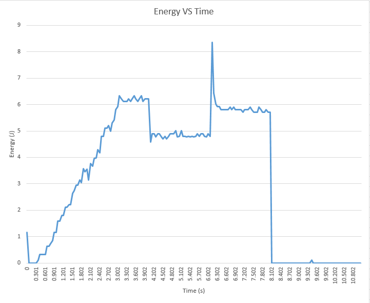
Using the same reflector test as from the previous lab, movement and functions were deemed normal and testing of the design was implemented. The AEV moved about a predetermined track and intended to move forward and then slow to a stop. Due to imbalance of the prefabricated design, the device was unable to generate enough power to move the AEV forward, but was able to reverse the vehicle. The following graphs depict the power and energy levels of the AEV as it moved along the designated path. The data was extracted from the Arduino and then extrapolated in a pre-made program to convert the data into tables and construct a graph of the data. The data is skewed due to the inability of the device to move forward and must be taken into consideration upon analysis.
Following data extraction, the process of redesigning the AEV were underway. A newly fabricated part was created for presentation for a possibility of grant funding.

February 12, 2019
Presentation amongst an audience of peers was conducted in order to secure grant funding of the new part. The part presented by the team was a 3D oriented design that primarily utilized elements from Individual Design 2. A pre-constructed body the had built in motor mounts on the underside of the vehicle to reduce the need of material in mounting. Additionally, a pre-fabricated battery storage space is placed up front to counter act the excessive back drop experienced in the trials of the previous lab. The overall piece would reduce the weight of the vehicle and displays little disturbance for air flow over the device.

Motor Configuration
March 1-5, 2019
Tests on motor configuration were conducted to find the most optimal configuration of motor mounts for a designated system. Utilizing the original prototype design, which had the motor configuration of motors on same plane as the prototype design above, motors were ran at 40% power and compared distance of each over the same time period. It is to be noted that the terms “Forwards” indicates a pusher style of movement and “Backwards” indicates a pull style of movement.
The first test conducted had 1 motor in the push method at 40% power. The following graph shows the data collected from the test and the distance traveled.

The push style of motor test resulted in a modicum of distance traveled at a moderate speed. The AEV traveled an estimated 1 meter in 7.80 seconds.
The second test utilized a pull style method with 1 motor at again 40% power. The following graph displays the testing results.

The pull style of motor usage resulted in a significant difference in performance that is greatly improved over the push method. As shown above, the AEV traveled an estimated 4 meters in the same time period of 7.80 seconds. It is to be noted that consideration to use a pull style for selections of the task to carry the heaviest of loads for the main task.
As the AEV is to have 2 motors, configurations containing both motors are used again at 40% power over the same time interval. The first of test of 2 motors uses the push method of movement. The test results are displayed as followed.

The push motor system as demonstrated above yielded results that were almost identical to the 1 motor pull system with an estimated 4 meter distance traveled in the 7.80 second time frame that was given. The results further supported the statement of using a pull style of travel for the heavy handling of large cargo.
Finally the pull dual motor system was tested and the following results were gathered below.

As shown from the data gathered above, the pull motor system has confirmed the statement of its efficiency. The data gathered yielded results of an estimated 7 meters being traveled in the 7.80 second time frame.
In addition to the distance per time gathered, each system configuration had data collected for Energy per Unit of Distance Traveled and Power per Time. The motors were ran at 40% power and maintained the time interval of 7.80 seconds. The term “Forwards” indicates a Pusher Style configuration and “Backwards” indicates a Pull Style of configuration.
In order to maintain consistency with the previously gathered data, the same order of Motor configuration is listed. The following is data for the 1 Motor Push Style.

The energy results gathered indicate the energy levels that were present during the testing trial of the Motor Configuration. The above results gathered show a relatively high energy output between 20 and 25 Joules of energy, close to 23 and 24 Joules. Based upon the designs, this will act as a basis for comparison for power and energy. The energy efficiency number is an estimate 21.359 J/m, a very low number in efficiency.

The power output for the motor configuration is displayed. The power output begins above 1 Watt in order to get the AEV to move then compensates as the AEV begins to move with power rising until 2 seconds where it remains at the level of 6 watts until it drops off to 0 at 5 seconds.
The data recorded is for the 1 Motor Pull Style of configuration.

The energy recorded of the Pull method of 1 motor indicates a lover energy output than the previous test in the push method. the energy output is less than the Push however the difference is only an estimated 1-2 Joules, still lying between the 20-25 Joule range in the latter half of testing. The energy efficiency of this particular system is an estimated 5.50 J/m, using less energy than and thus more efficient than both push systems of either motor configuration.
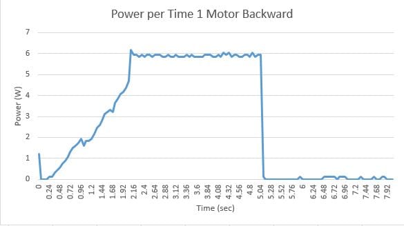
In compared to the 1 Motor Push system, the power output of the 1 Motor Pull system is less than 1 Joule different. It is estimated that the difference in power is on average 0.2 Joules and is not considered to be an important factor in change.
The data recorded is for the 2 Motor Push Style of configuration:

Based upon the previous motor configurations, singular motor configurations are found to utilize less power and energy over a period of time and space within the pull method. With use of 2 motors, there is an obvious improvement in the energy efficiency of the AEV over the usage of 1 motor no matter the orientation. The energy usage over time was an estimated 10.230 J/m, and can be compared to the dual motor pull system.

The power usage within the new motor configuration is an improvement over the less efficient 1 motor configurations. The average power usage over the 7.80 second section shows the necessary increase to get the AEV moving and the average usage at 12 watts over the course to maintain the consistent power usage until the motors are cut.
The following data is the recorded results for the 2 Motor Pull Style configuration.

The final configuration supports the previous statement of the efficiency of the 2 motor pull system from the distance over time section. The energy efficiency, although using more energy than the 1 motor systems, the energy efficiency number resulted on average to be 6.429 J/m, comparable to the single motor pull configuration.

The power output of the dual motor pull system was found to be the most efficient system and usage is advised in the pulling of heavy loads.
Reflective Sensor Testing
March 6, 2019

Accuracy of the reflective sensors using the standard configuration was not impacted in any major way with or without a cover present. The total difference measured over five trials each (10 total trials) was only 0.2 marks. However, there was less variance between the results of each trial with the cover than without. Considering the results of the test, the cover has been determined to be unnecessary, and may ultimately hinder performance with its additional weight and the risk that it poses to disrupt the wheels on the track. Another test of the sensors was performed, involving the use of a spacer. Five trials with the spacer were run, with the results varying as much as 60 marks, with an average distance 16.62 marks less than the intended distance. Due to the lack of reliability that the spacer provides, especially compared to without, adding a spacer would be poor judgement, only serving to hinder the performance of the AEV.
Picture of light cover used during experimentation stages


March 8, 2019
Performance testing for the original AEV design was undertaken in order to test timing and positioning of the AEV through a mock of the first part of the final trial.
Propeller Orientation
March 19, 2019
Conducted tests on propeller orientation after finding differing results in motor configuration from other teams conducting AEV design project. Propellers oriented with serial numbers faced away from AEV and at the top of the propeller and serial numbers at the bottom of the propeller. Tests conducted in running AEV on same track and power to compare efficiency of the orientations.
It was found that the original orientation proved to be more efficient than the flipped designs, but marginally more.

Flipped pull design that was found in the experiment.

Regular pull design that was found to be more efficient than the flipped design.

Flipped push design from the experiment.

Regular Push design that was more efficient than its flipped counterpart.
3D Body Printing
March 26, 2019
Constructed AEV with 3D printed body. Will be used in third aR&D testing for weight differences and implications of using 3D printed material.

March 29, 2019
Testing of the new 3D configuration went through first testing trials. Tests conducted in 2 motor push style configuration for testing.

The above graph depicts the Distance in meters per Time in seconds in the 2 motor push style configuration. The initial test resulted in am estimated 6.5 meters in a 12 second testing frame. Compared to the data gathered for the previous design of the same style, the new 3D design performed better than the old design. The old design traveled at 0.513 m/s while the new 3D design traveled at 0.5397 m/s.

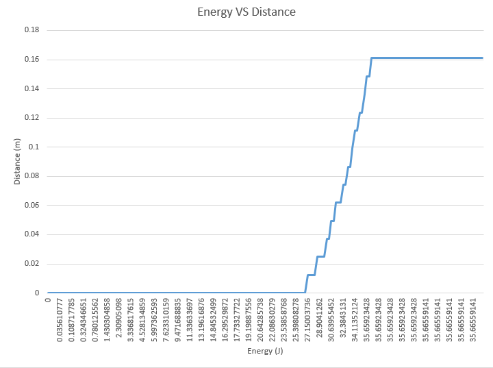
The above graph depicts the Energy vs. Distance for the above AEV design. The 2 motor push configuration compared to the old AEV had an energy output of 10.233 J/m. The new AEV design with the same configuration and style performed better than the old design, resulting in an average energy output of 9.45 J/m; an energy efficiency increase of 0.783 J/m.
April 2, 2019
Modified the 3D design into the current design below.

The new design features a T arm for stability and balance as well as a balance of the Arduino further back in the main plane to supplement balance.
April 5, 2019
Experiment with servo motor stopping system that utilizes mounting putty as the stopping material. Inconsistent breaking distances are noted and vehicle may stop short of destination even with added marks. Repeated testing will note an improvement in stopping location and the new code must be adapted and tested to perfect the procedure.
April 9, 2019
Servo Motor continued to be inconsistent despite repeated testing. Servo Motor had proven unreliable for the Final Performance Test and was promptly scrapped. The reverse propeller method for breaking was reinstated in the final design and used in final tests.