Welcome to the documentation materials for my Makey-Makey exploration project. The gist of the experience is a hexagonal puzzle that uses Makey-Makey circuits and contacts to combine digital feedback with a physical component. This documentation is written through the cycle process. Cycle 1 is the first check-in, and Cycle 3 is the final check in and final version of the project. You will find posts are ordered in a reverse-chronological order, with cycle 3 appearing first but being the last iteration of the project.
Cycle 3- Final Product
The ending of this project was particularly frustrating because I ended up getting COVID the last week of classes. Yes if you’re reading this 20 years in the future, COVID was a terrible virus that crippled most of the planet in 2020, and we are now living with it every day. Because of this, I was not able to present my final prototype to the class, so a part of this documentation post will include a short video demo on how my game works!
The final project was a great prototype that I am very proud of. After refining some of the cable setups and improving the stability of the Makey-Makey board, I was able to get most of the contacts working. Because of the way I glued and reinforced the wires, some of the contacts cross over, so some will activate more than 1 “keystroke” on the Makey-Makey. Combining this with the digital experience I created on Isadora yielded a pleasing result that was an excellent insight into how different microcontroller boards work.
Reflecting on the Build Process
Building and testing Puzzlr was no easy process. It involved a lot if iteration through different laser-cut prototypes and testing scenarios. I learned how to wire-up and configure the Makey Makey within Isadora, and had to design a circuit system that would work with the Puzzle style.
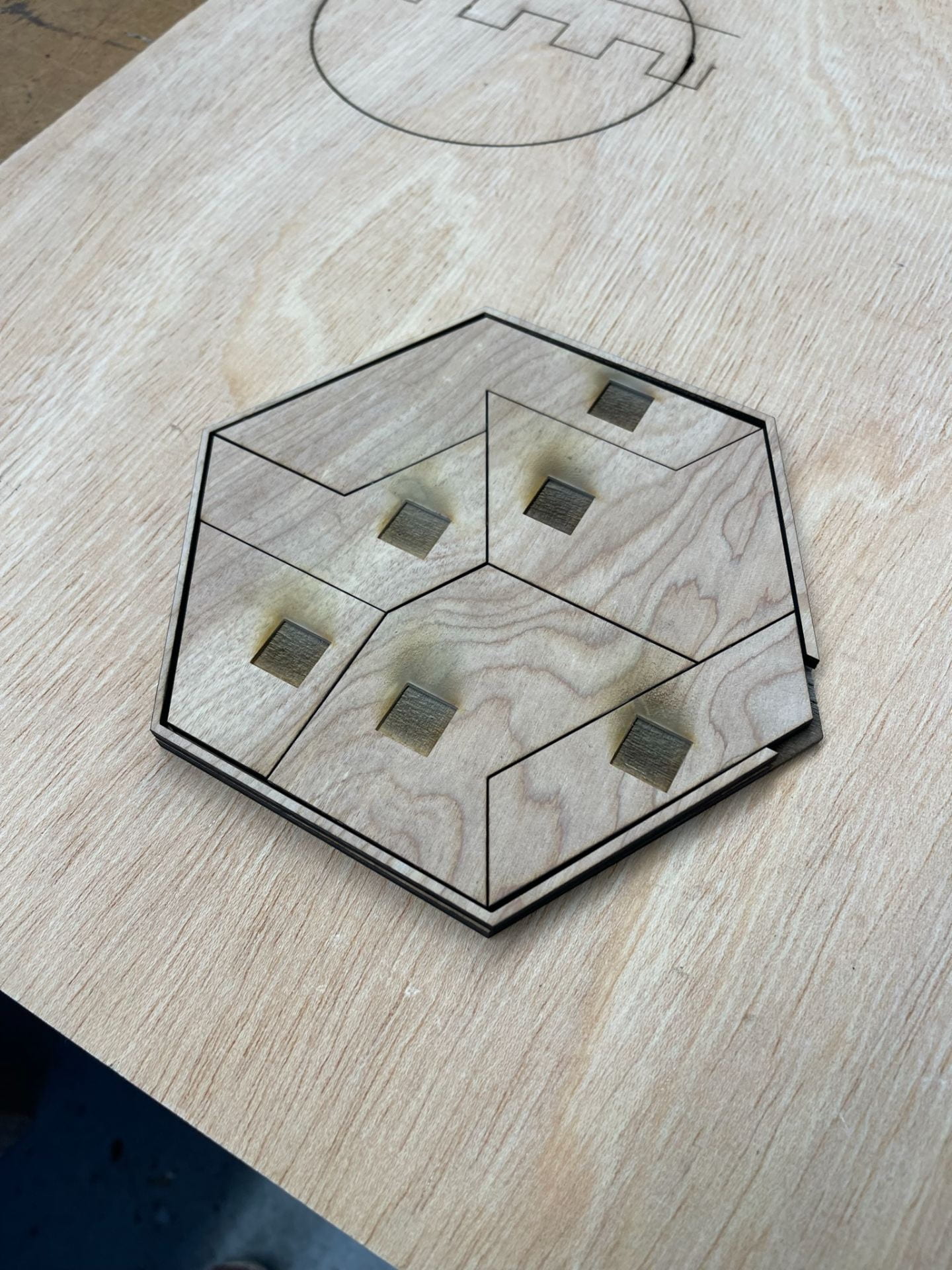
The first wooden prototype allowed me to test the setup and whether the puzzle would be hard for others to solve. It turned out to be a n excellent learning moment because I ended up adjusting the thickness to actually fit the wires, and even learned that I had to flip the puzzle pieces to get the correct engravings.
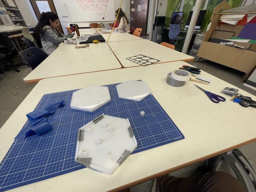
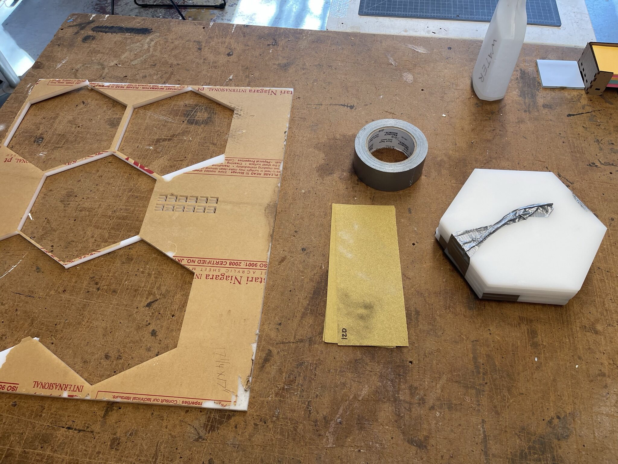
The second and final prototype involved laser-cutting the puzzle out of white acrylic. Then I sanded everything down, cleaned it up, and put it together with duct tape. I would have glued it together but I needed constant easy access to the wire housing to make adjustments and improvements. Another hurdle at this stage was sanding down the circuit clips that hold the wires together. They were initially too tall and ended up poking through the holes; I had to sand them down so they would remain flush with the upper level. By using tin foil, foil tape, glue, and duct tape, I was able to put everything together and get the circuit completed.
How the Game Works
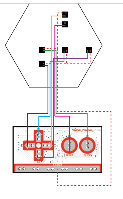
Here is a picture of the actual schematic I created for the puzzle board. The goal of the game is simple: get the pieces onto the board and in the right spots. Each puzzle piece has a piece of metal foil tape underneath it that corresponds to the black squares on the schematic. When the piece makes contact with the board it completes each circuit by closing the loop between the ground and input wires. Each contact corresponds to a certain input on the Makey-Makey, and when activated will relay a keystroke to the computer.

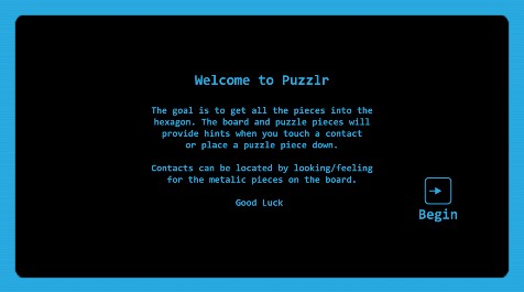
Starter Screen
Instruction Screen
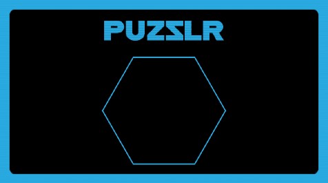
Game screen. As pieces get placed on the board, they begin appearing here. If they are removed from the contact, the piece will disappear a few seconds after it is no longer receiving an input signal.

Win screen
Video Demo
Reflecting on the Project
I really enjoyed this exploratory project because it allowed me to experiment with something I was considering for my thesis. The Makey-Makey system is really unique but has it’s issues with more robust and complex applications. If I were to change anything about this project, I would have spent some time learning how to solder so the connections could be a little stronger. I will be applying the things I learned during this project when creating my own microcontroller input methods for my thesis in the future!
Cycle 2 – November 25th
Not too much has changed in the actual design of my project since the Cycle 1 check-in. I’m still working with a unique and fun way to create physical input methods that match a digital experience. My overall goal is applying the knowledge I gain from this project to my final thesis. So far there have been a few hiccups and issues, but I’m incredibly happy with the progress I’ve made and I look forward to finishing the project soon.
Progress Update
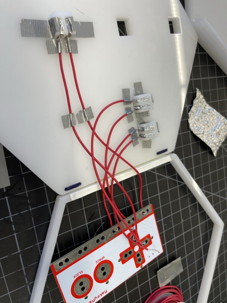
Most of the photos that will be in this Cycle 2 post will be work-in-progress shots of me laser cutting the final pieces, sanding them, and building up the puzzle system and circuits. The last few weeks have mostly been spent refining and building my puzzle board, as well as experimenting with some simple Isadora elements. The final puzzle board was laser cut from white acrylic, and assembled using duct tape and super glue. The new board design came as a result of a lack of space on the first prototype; this version is much more stable, and includes a bottom space for circuits, a mid plate where the puzzle pieces sit, and then a border to help keep the puzzle pieces in. I also created a simple circuit system where the two wires meet under the contact point, but are separated by a plug-like shaft. Each side extends up into the board and splits into two contact points, the puzzle pieces themselves have metal foil underneath which complete the circuit when placed correctly.
Next Steps
As the project nears it’s end, I’m currently refining the circuit setup and improving the connection quality. I’m planning on including a simple visual component that will provide progress feedback to the player. Since that is an important part of my investigation into hand-eye coordination, I will be prioritizing the Isadora interface to get at least some feedback from that area of focus.
Cycle 1 – October 27th
Project Brief
For the final project in my Devising Experiential Media Course, I’ve decided to create a fun and challenging puzzle that will stimulate the player in a variety of different ways through 3 distinct play modes. The puzzle consists of six pieces arranged in a hexagonal shape. The goal of each level will be to complete the puzzle each round while navigating the changes in the sensory elements of the puzzle. My research thread focuses on microcontroller inputs and the conceptualization of touch, so I see this project as a way to explore creating micro-interaction systems through physical objects. The first round of the puzzle will be basic; the player just has to complete the puzzle by getting all the pieces onto the board in the correct configuration. The contacts on the bottom of the pieces and the board itself will give a slight hint as to how to approach the puzzle (more on that later). There will be both a visual and auditory feedback component informing the player about their progress. The second round will involve covering the players hands so that they can only use the visual/auditory feedback from the system rather than looking at their hands. The pieces will also include unique textures that will then be mirrored on the screen to guide the player on what textures go where on the board. The third and final round will involve blindfolding the player so they will have to rely on the textural elements of the pieces coupled with the auditory feedback. In this section, the auditory feedback for each piece will be unique so players can keep track of what pieces go where. This final level is intended to be very difficult and will be used mostly as an experiment. 
Production & First Prototype
For the first phase of iteration I created a schematic and then used it to laser cut a preliminary model of the puzzle and circuit housing. After laser cutting and setting everything up I realized some parts of the first prototype need to change:
- The engravings on the bottom plate are too narrow and can’t house the wires and cables necessary for the puzzle piece contacts.
- The engravings on the bottom of the puzzle piece are on the wrong side of the pieces because I forgot to flip them before printing
- The circuit layout is confusing, and requires more thought into how the ground/input wires are going to be set up in the final board.
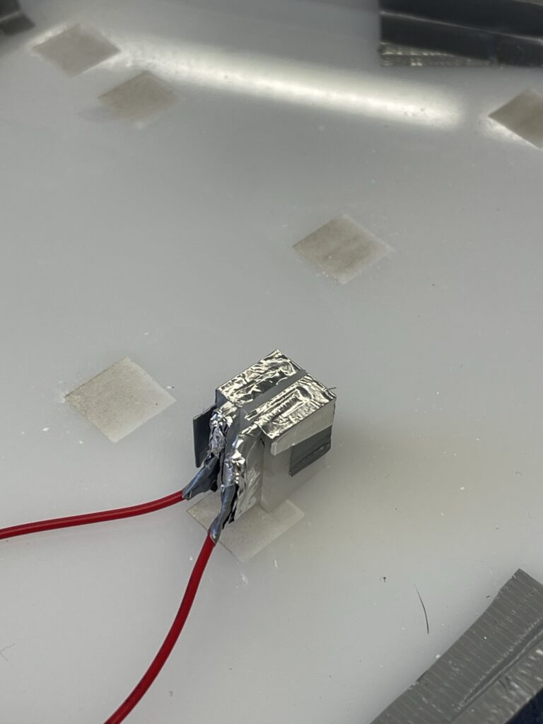
After thinking about those changes I modified the schematic and created a new one featuring a new build layout, a new circuit component, and a new circuit layout. I decided I would create two levels to the puzzle, one for the circuits and one to put the puzzle pieces on. This allows more room for cables and components under the puzzles, and ensures a clean look on the top. The new circuit component is a little adapter (in the middle of the schematic) that will serve as a bridge between the circuit housing and the top of the puzzle. The component will take the ground and input cables and attach them to two pieces of foil that are sticking out at the top, the puzzle piece will then have a piece of foil underneath that, when placed on the contact, will complete the circuit.


Next Steps & Connection to Thesis Research
The next step in the project is to make the second prototype and get the circuit laid out and working for the next cycle! This connects to my research thread by allowing me to explore and get comfortable with microcontroller systems. I’m experimenting with fabricating physical interaction methods that will translate into digital inputs and connections for my future thesis experience. I plan on combining what I learn in this project with what I learn in my explorations of haptic gloves into a final experiment next semester before beginning thesis production.