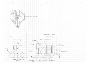
Below are the three final ideas for the robot that were used in the scoring matrix.
Idea 1
- This idea features the use of four omni-directional wheels in an X configuration. Two of the opposite wheels are connected by an axle and driven by one motor. The other two wheels are driven individually by their own motors. Task completing mechanisms include a vertical, sliding PVC pipe with a magnet to control the cargo supplies, a stationary arm for the switches, and a sliding panel for the fuel button. A layout drawing of this design is given in the image below.
Idea 2
- The second robot layout featured a two wheel drive, two motor system on a rectangular PVC sheet. The rear wheels would be enclosed in the rectangular sheet, and a skid system would be placed on the front of the robot. Some designs that would be used to accomplish the tasks include a T-shaped arm for switch toggling, a horizontal PVC pipe with a magnet, and a checkerboard design on the front of the robot to press the fuel buttons. An image a SolidWorks model of this design is given below.
Idea 3
- This design features a PVC-base chassis being driven by a tread system. The drive wheels would be located above the wheels on the ground in order to maintain tread link tension. The design ideas that would be implemented to complete the tasks include a rotating lever that presses either the red or blue button depending on sensor data, a forklift design for the cargo supplies, and a vertical shaft with a falling arm to handle the switches. A layout drawing of this design is given below.


