Reflectance Sensor Setup
Proper sensor setup is critical to the performance of the AEV throughout to duration of the tests and project. The proper setup is displayed below

Exercise 4:
The following code was tested to practice setting up code, testing the code, and documenting the results.
celerate(4,0,25,3); //accelerate both motors to 25% in 3 seconds
motorSpeed (4,25);//both motors are at 25%
goFor(1);//all motors go for 1 second
motorSpeed(4,20);//set all motors to 20 speed
goFor(2);//all motors go for 2 seconds
reverse(4);//change direction of motors
motorSpeed(4,25);//set all motors to 25%
goFor(2);//run for 2 seconds
brake(4);//stop all motors

The incline between 0 and 3 seconds represents the code that is commanding the motor to accelerate to 25% power in 3 seconds. The 0 slope between 3 and 4 seconds represents the motors running at 25% power for 1 second. The 0 slope suddenly shifts down to about 4.33 Watts because the motors were coded to run at 20% power. The sudden spike in the graph represents the reverse command, and the 0 slope that is approximately collinear to the 25% power line is executing the 25% power command. The power suddenly shifts to 0 as the brake command is given.

The 0 slope at the beginning represents the distance covered when the motors were running at 25% power. The 0 slope at 4.33 Watts shows the distance covered when the motors were at 20% power. The spike represents the instantaneous reversal of the motors. The motors travel a distance at 25% power; the motors shut off and a small distance is covered as the brake command is executed.
Designs and Evaluation:
The AEV sketches of each group member (Dhan, Michael, Keaton, and Andy) will all be placed here, along with their explanations of drawings. This was done to try and discover a design that will be used in future testing and data collection.
Andy’s Drawing:

The pros of this design is the light weight and the constant weight distribution. This will help in providing consistent and usable thrust to keep the AEV on course. Sadly with the propellers being on the back of the AEV the small propellers will have to be used reducing thrust.
Keaton’s Drawing:

This design is beneficial because of its slim design. The design’s balance is questionable and this would cause problems in the area of energy efficiency.
Michael’s Drawing:
The design is compact and powerful. The design falls short in efficiently using the energy source provided to it, however.
Dhan’s Drawing:

This design has balanced and light weight that helps to run ave faster in incline plane with less energy.
Evolved Design:

This design find the perfect balance of utility and efficiency. The design is cost effective and lightweight. The purpose of its orientation is to maintain balance in order to appropriately use energy to accomplish the task.

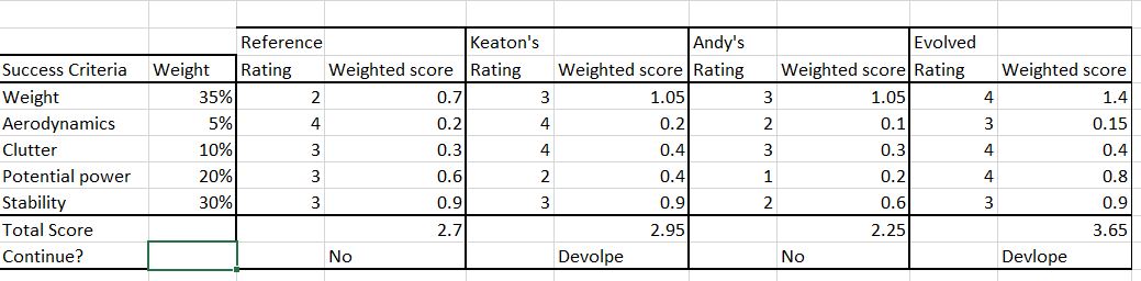
In the above pictures we addressed what we deemed to be the most important aspects of the AEV design. This includes weight which we concluded to be the most important aspect as it would affect energy efficiency and overall cost. The second aspect is aerodynamics which we concluded to be the least important aspect because the AEV moves at a low speed. The clutter component is slightly important because if there is too much clutter in an AEV then wires or other materials can negatively impact the success of the AEV. Next the potential power aspect of the AEV impacts how efficiently power can be used and how much total power can be generated. This is important since the AEV has to move up inclines with cargo. The stability of the AEV is very important since if the AEV is not balanced or stable that could negatively affect its safety and energy efficiency.