DAY 2
STUDENT’S NOTES FROM THE CIRCUIT PROGRAM


Student notes were taken to remember what they learned about simple circuits and their paper circuit project.
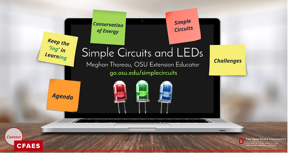
Simple Circuits with Meghan Thoreau, OSU Extension Educator, and Judy Walley, Teays Valley Chemistry Teacher. Full presentation link: go.osu.edu/simplecircuits
Why Understanding Simple Circuits is Important?
Basic circuit knowledge is important for many different disciplines, including engineering, physics, chemistry, and mathematics. It’s also useful knowledge around this time of year when you may need to repair a string of old holiday lights? Understanding and building simple circuits show us important concepts learned in school that can describe useful real-world systems, like devices we use every day, cell phones, light switches, Chromebooks, cars, etc.
The electric charge that flows through your house is called your electric circuit. This carries useful energy through your house that you can transform into other forms of energy to do various tasks. The US standard household circuit has an effective voltage that takes 120-volts. Volts represent the energy per unit charge. We discussed these basic building blocks of simple circuits in STEM Club this month. Our hands-on simple circuit design challenge uses 3-volt lithium batteries. Before jumping into our design challenges we’ll cover a few basic circuitry concepts and energy principles.
For program presentation, click here.
Conservation of Energy, First Law of Thermodynamics
The conservation of energy principle was discovered and published by Julius Robert von Mayer in 1842. Mayer was a German physician, chemist, and physicist and one of the founders of thermodynamics. However, there were many others working in the field that made significant contributions, such as, James Prescott Joule, Hermann von Helmholtz, Alessandro Volta, and Benjamin Thomson.

The principle of conservation of energy is an effective tool in solving problems and understanding how different forms of energy directly impact our lives. There are also benefits to this principle. These include recycling of materials, lower energy costs for consumers, less pollution due to a reduction in the use of fossil fuels, and less harm to animals and the environment. We watched a short video, from Two Minute Classroom, that explained the basic concepts of how energy transforms itself into other forms and never truly disappears or is destroyed.
Below are 10 common types of energy:

Atoms and Electrons
Judy Walley led students through the basic concepts of atoms and electrons, because, without the flow of electrons, we have no electric circuit to work with.

Judy Walley explains the basic concepts of atoms and electrons as students formed a single circuit where electrons passed through them to power a sound buzzer.
Walley also explained the chemistry of a battery and how chemical reactions occur inside the battery that causes an imbalance or a build-up of electrons (-) on one side of the battery over the other, hence why one side or one terminal of the battery is negative (-) and the other positive (+). We also introduced the basic materials for our hands-on design challenges and explain how a battery works.

Screenshot from our virtual simple circuit presentation.
How a Battery Works
Batteries are important to everyday life. Batteries are essential to most electrical devices. They exist in our cars, cell phones, laptops, and other electronic appliances, and serve as critical backup sources of electricity in telecommunications, public transportation, and medical devices. A battery is essentially a container full of chemicals that produce electrons (-). Inside the battery itself, a chemical reaction produces the electrons.
The battery is a device that stores chemical energy and converts it to electrical energy. The chemical reactions in a battery involve the flow of electrons from one material (electrode) to another, through an external circuit. The flow of electrons provides an electric current that can be used to do work. In our case, students use copper tape to build a paper circuit to create light energy with an LED. Below depicts the inner wors of a battery.

Screenshot of how a battery works from our virtual simple circuit presentation.
The students learned that a battery has three main parts: an anode (-), cathode (+), and the electrolyte that separates the two terminal ends on the battery. We discussed the chemical reaction happening inside the battery that causes electrons (-) to build up on one side of the battery causing one end to be negatively charged (-) and the other end positively charged (+). This buildup causes an imbalance of electrons (-), that want to travel to the other side of the battery, but can’t move freely until a conductive circuit is completely looped for the electrons to travel through; in our case, the conduit is copper tape.
When a circuit is complete, or a loop created, the electrons will flow through the conductive paths racing to reach the other side of the battery terminal. When the electrons flow through the loop, the chemical energy inside the battery is transformed into electrical energy running through the circuit. When all electrons (-) make it to the other side, the battery stops working. All of the electric energy was transformed into other forms of energy.
Electrical energy allows us to do work by transforming energy into other forms. We use LEDs in our paper circuit design challenge because it’s a simple way to show how electric energy is transformed or converted into light energy. We could replace the LED with a simple motor and the motor would convert electrical energy into kinetic.

Screenshot of simple circuit components and electricity concepts from our virtual simple circuit presentation.
What’s a Diode?
Both LEDs and motors can easily be added to simple circuits. However, LEDs are somewhat more restrictive than motors, because LEDs are diodes. A diode only allows current to flow in one direction. From the cathode, (-) leg of the LED through the anode (+) leg. Note that the anode on a battery is negatively charged, but the anode on an LED is positively charged! The correct way to connect an LED legs to the battery terminals is positive to positive/anode to cathode and negative to negative/ cathode to anode. Study the image above if this is confusing. If the LED or battery is flipped in the wrong configuration then no current or electrons flow through the LED because the diode only allows for current to flow in one direction.

Image source: https://diotlabs.daraghbyrne.me/docs/controlling-outputs-motors/diodes/
A motor does not have a diode, therefore current can flow in either direction, and depending on how the motor is connected to the battery will decide what direction the motor turns left/right, or moves forwards/backward.

Image source: https://www.robotroom.com/DPDT-Bidirectional-Motor-Switch.html
Electric Circuit Design Challenges
As a virtual group, we challenged ourselves with a few NearPod activities to reinforce our electricity concepts before beginning our hands-on paper circuit challenges. A paper circuit is a functioning electronic circuit built on a paper surface instead of a printed circuit board (PCB). Projects can range from greeting cards to origami, to traditional art such as paintings or drawings. STEM totes went home with the students and included paper circuit design challenges and supplies.
Supply List (we purchased all our supplies through Amazon)
- LED
- Conductive copper tape
- Plain card stock, or templates printed on card stock
- 3-V coin cell battery
- Tape (not included)
- Binder Clip
Other useful items: multicolor/print card stock, glue stick, scissors, pencils, markers

Teays Valley High school mentor, Julia Kudar, assisting elementary students with our paper circuits program.