
Overview
Last summer (2013) I tried occupying my time by working on a personal project. Up to that point in time, I had done a lot of programming in various languages but had never worked with electronics and hardware which make the software possible. For that reason, I started searching for a cool project that would teach me the basics of circuits. After searching the internet for potential ideas, I discovered something called electroluminescent wire (also known as EL wire). EL wire is a fairly unique source of lightning due to it’s ability to flex, bend, and be shaped in just about any way you want just like regular wire. The entire strand of EL wire is mostly a copper wire coated in a phosphor that lights up with AC current flows through it. I decided to make this the basis of my project since I really liked the projects I saw online involving lights such as LEDs.

So as I’m looking more into EL wire and how it’s currently used, it hit me. Before the summer was my freshman year at Ohio State and I made it a goal with my friend to go to every Ohio State home football game that year. And so I did believe it or not. Although I loved watching the actual game, my favorite part of home games was Script Ohio. A project was born. I decided I would use EL wire to create a Script Ohio sign that is identical to the march formation performed by the Best Damn Band in the Land. However, I knew I had to integrate in some cool features so it wasn’t just an art project.
Before this point, I had seen a couple of projects that focused on sound reactive lighting. As music played in the background, the lights would pulse to the beat. I knew this is where I wanted to go. A sound reactive Script Ohio sign to hang on my wall. The project was set and now it was time to research ways into how I could accomplish my goals. Due to never this being my first electrical project, I was very uncertain on how to begin. Therefore, I started pulling ideas from others using EL wire and sound to make their own projects. I quickly learned that many people were using an Arduino to help process the background sound and turn that into a signal for triggering their lights. So I slowly gathered a list of supplies I thought I would need, and started sketching out how I envisioned the circuit.
The Circuit
Since I only had software experience at the time, I figured the best chance I had at making the project a success was by using a microcontroller I could program to do the hard portions of the circuit for me. Using this is at the starting point of the circuit, I decided I needed the following components:
- 1 DC Plug Female
- 1 5V Power supply
- 1 Flip Toggle Switch
- 1 Push button switch
- 10K Ohm pot
- SSR 8A
- Various resistors
- EL wire inverter
- ~10 feet of EL wire
- Analog Sound Sensor
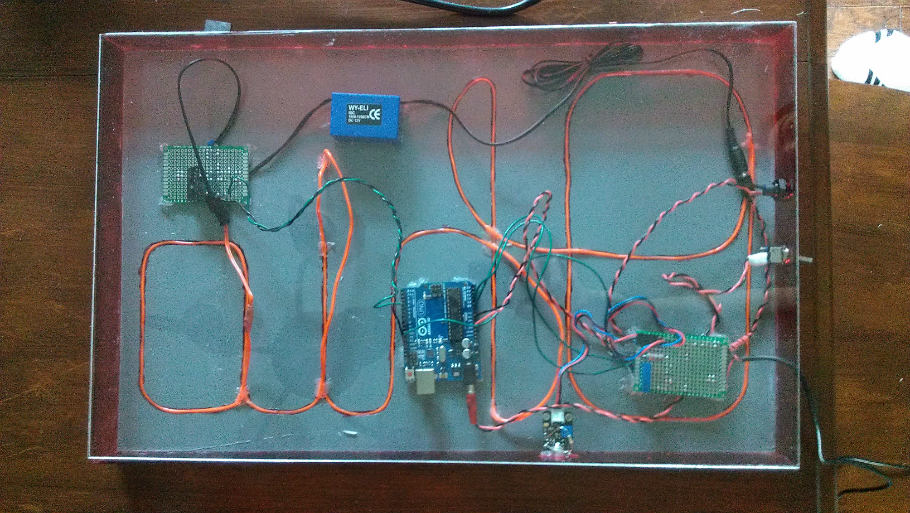
You can see overall circuit layout on the back of the sign. To protect it from anything that might accidentally short circuit or damage the circuit, I decided to enclose the entire back and sides of the sign by using acrylic plastic sheets cut to size. There are four main components to the circuit. The first major component is the Arduino which can be found in the middle of the board. Next, is the prototype board located on the left side of the board. This board was responsible for taking in an input signal by the Arduino and either closing or opening the circuit that the EL wire was on. Since EL wire is ran using AC and the rest of my circuit uses DC power, the circuits had to be isolated. This is where the SSR and the inverter (blue box) came into play. The inverter takes in 5v DC and converts this to 120V AC. I then cut the output wire of the inverter and passed it through the SSR. Now, when the Arduino was told to send a small voltage to the SSR, the SSR gate would close, and the EL wire circuit would also close causing the EL wire to light up.

The green wire is the gate input which triggers the SSR to close
But before the EL wire circuitry could work, I had to determine a way of supplying 5V. To complicate things a bit more, I also had to power the Arduino off the same 5V power supply and I also wanted to introduce a few switches in order turn the sign on and off without having to disconnect the power supply manually. Therefore, I needed another prototype board to help mount the last few components and to help split the 5V input off into various lines. In order to split the power supply into multiple parallel lines, I weaved 2 copper wires in a straight line on the circuit board to act as a 5V and ground line. This then allowed me to directly solder the other power inputs directly onto these lines. I however had to be careful not to allow any copper to accidentally fall across the two lines and short the circuit. I had a little bit more room on the board so I decided to also store my potentiometer on this board. This 10K pot is an analog input for the Arduino. Depending on the how the turn knob on the pot is positioned, a voltage will be sent to the Arduino which is then converted to an integer between 0 and 255. 0 being that the pot is completely closed and there is no voltage coming through, and 255 meaning there is 5V coming through the line. This integer is then used in software to determine how to scale the sound coming in from the sound sensor.
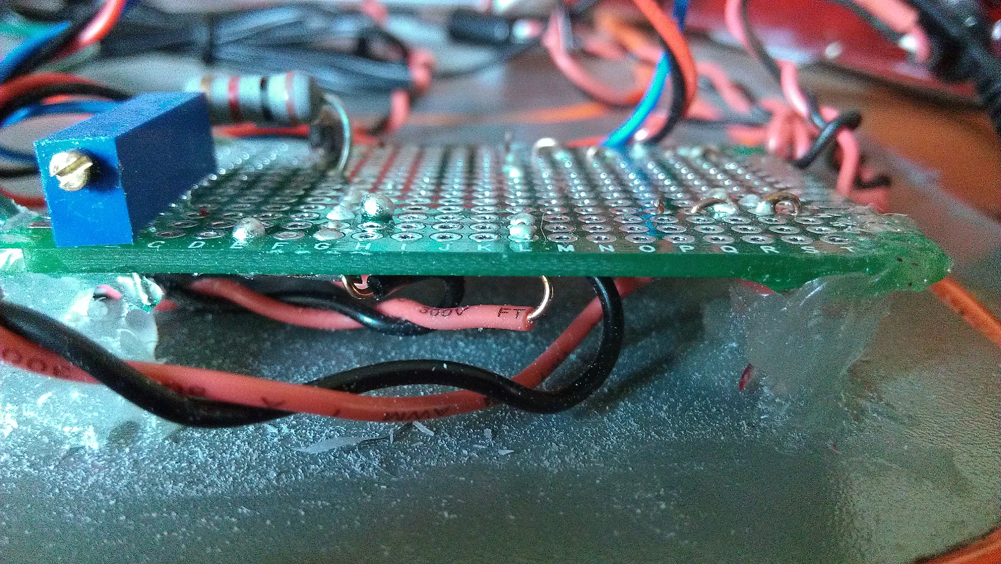
Side view

The other side of the second board which splits the 5V input into various outputs and holds the pot responsible for controlling the sensitivity of the sound sensor
Connected to this board was also two switches. The flip switch as seen in the above image was used to turn the entire sign on and off. The other switch was used to switch “modes”. Although I thought a sound reactive board would be neat, I wanted to have the ability for the board to light up in a quiet room. Therefore, I programmed the Arduino to have two modes. One mode was sound mode and the other was the default mode. When the sign first was turned on, the Arduino was programmed to constantly power the EL wire so that it always lit up. Then, if the button switch was hit, the Arduino would switch to “sound mode” which would only turn on the EL wire when it detected a sound above a certain level. These switches were mounted to the side panels of the sign for easily access at all times.
The Sign
Once the circuit was tested and I determined it was truly working, it was time to focus on how I was going to contain all of these into a sign. I also had to consider what I wanted the sign to look like. To start, I wanted to hide all the components and the wire out of sight. Also, since the layout of Script Ohio is not entirely continuous without overlaps, I had to determine a way of hiding portions of the wire. First, I start laying out the wire in the best Script Ohio shape I could achieve.

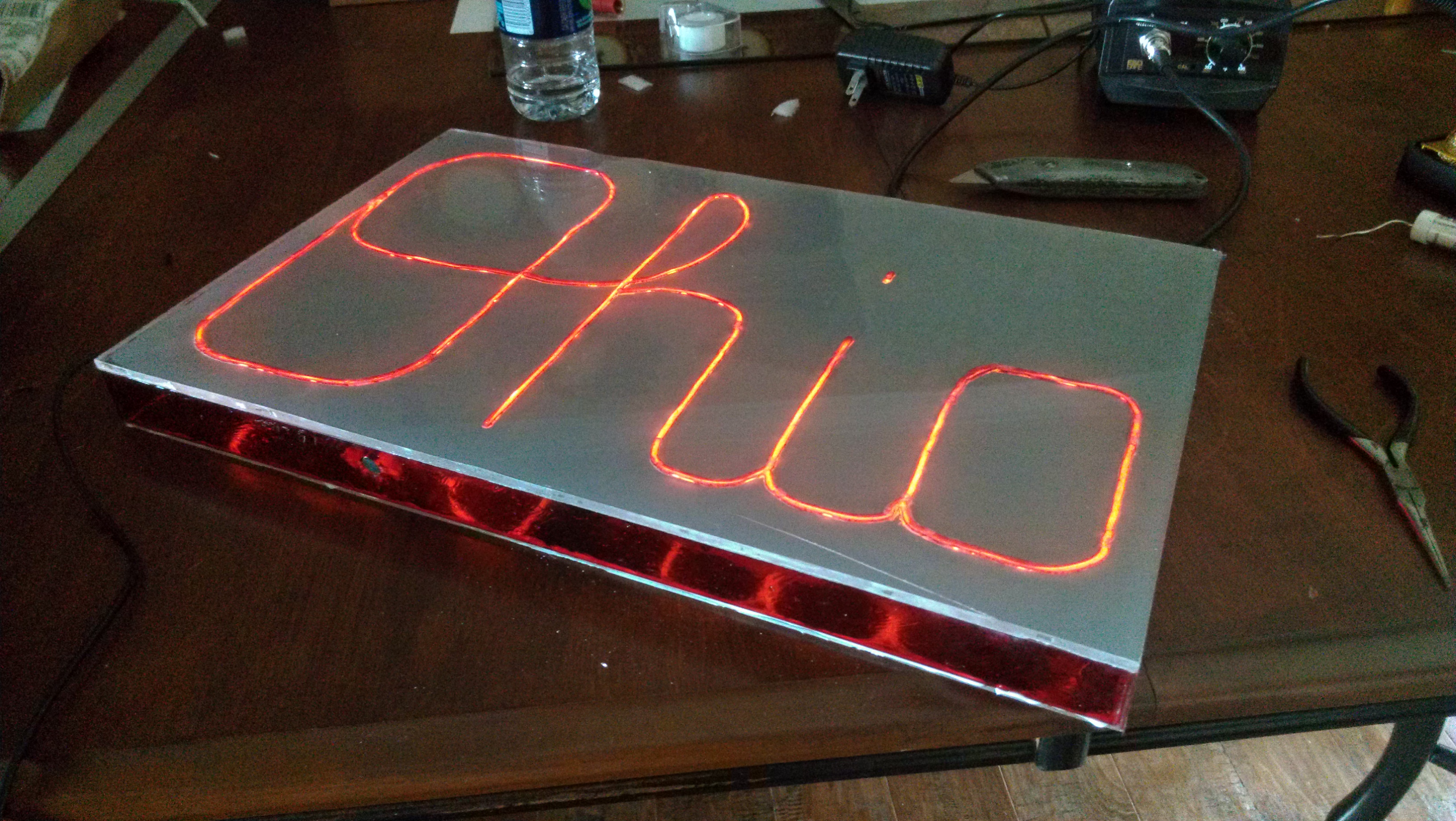
Once I was happy with the overall layout, I focused on hiding the parts of the wire that I didn’t want others to see. Since acrylic is clear, I decided I would have to paint over the sections of the front that I didn’t want light coming through. Therefore, I went out and bought some gray spray paint and went over one side a few times until the light no longer was able to pass through. At this point, I decided to carve out the sections of paint that I wanted the light to shine through. This became very trial and error as I cracked and destroyed multiple pieces of acrylic sheets trying to do so. After taking my time, I was finally able to carve out the sections I wanted. In went the wire and silicon was used to temporary glue components to the back as needed. Now I had to focus on the side pieces. I simply drilled out holes for the switches and painted the sides with a transparent red paint. This didn’t turn out looking that sharp but I was quickly running out of funds for the project so I decided to use them anyways. I glued the the side pieces on and the final cover that goes on the actual back of the sign.
It was complete and I was content with how it turned out.
Check out this video to how it performs. I apologize for the poor video quality and sound. The EL wire has a quicker toggle rate than the camera I was using so it’s visually not the same on video.
Disaster
For months after, the sign worked properly and hung in my room. However, one day when I went to show a friend how it worked, it didn’t properly power up when I hit the switch. A bit confused, I figure a connection somewhere had came loose and that I wouldn’t be able to fix it at that moment. I put the sign down and forgot to turn off the power. As I’m having a conversation with my friend, we both realize we smell something burning. We start looking around but can’t determine where the source of the smell is coming from. I then turn around and see smoke coming from the rear of the sign. I grab the sign and see that the inverter is burning so I promptly disconnect the power. It however was too late since the inverter had already fried and in the process burnt a hole through the paint. Therefore, the circuit not only became nonfunctional but the enclosure was damaged as well.
I decided it was a good project nonetheless while it still worked and therefore decided I wasn’t going to try to fix it since I had used the entire budget I had for the project. So for the meantime, there is no longer a Script Ohio Sign. However, I plan to make the Script Ohio Sign v2 that will address all the parts of the final build that I was not satisfied with. Until then, I’m looking forward to doing more projects like this!