The Spring 2018 FEH robot course included a wide range of tasks for the robots to complete. Below is a list of each task accompanied by a short description of the requirements:
Car Jack: The robot must be capable of approaching a lowered car jack and raising it.
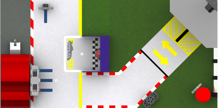
Control Panel: The control panel consists of three pushable buttons, the center of which activates RPS for the remainder of the run, if desired. The robot must drive its sensor over the light on the ground, which will dictate whether the robot is to push the left or right button on the panel.
Fuel Crank: The fuel crank is controlled by a spoked, vertical wheel that must be turned 180 degrees (plus or minus 20 degrees) by the robot.
Wrench: The wrench sits atop a stationary stand, and the robot must lift the wrench off of its base and attempt to deposit the wrench in the garage, which is located up a ramp near the fuel crank.
Final Button: Upon the completion of the aforementioned tasks, the robot is to return to the starting location and push the final red button to signify the end of the run.
The team brainstormed multiple ideas for each course component to provide a wide range of possible methods to draw from. Below is a list of the ideas and the team’s conclusions, organized by task:
Car Jack:
- The robot could be designed such that it could obtain the wrench first using a fork-prong design. Then, the wrench could be used to lift the car jack, effectively using one objective to complete another.
- The car jack could be used to lift the jack with a lever attached to the robot and powered by a servo.
- A lever powered by a motor could also be used to raise the car jack.
- Using an angled surface, the jack could be raised by simply running into it.
- A wedge could be used to perform in the same manner as a lever; this will reduce the need for another moving part.

As the decision matrix above illustrates, the most successful idea based on the team’s criteria was the forked lever powered by a servo, which allows the robot to raise the car jack while using the same forked lever for other components of the robot course, maximizing efficiency.
Control Panel:
- The panel buttons could be pushed with a movable arm or double forked prong design.
- The buttons could also be pressed with the wrench if it is picked up first.
- A wedge could be used to press the correct button, again reducing the need for another moving component.
- A panel could be erected on one side of the robot that could be used to drive into the correct button.
The forked prong mechanism is superior to the other ideas due to its flexibility. Not only can it press both the required button and the center RPS button simultaneously, it can be used to perform a number of required tasks throughout the robot course.
Fuel Crank:
- A rotating wheel could be mounted to the front of the robot.
- A peg could be attached to the bottom of the robot and oscillate from side to side.
- The robot could approach the fuel crank from the side and use the wrench to turn the wheel.
- A claw could be used to grab and rotate the fuel crank.
- A rotating horizontal gear can be used to interlock with the spokes of the fuel crank.

The decision matrix above shows that the use of a rotating horizontal gear attached to the bottom of the robot provides the optimal solution to the fuel crank component of the course. It is located in a different spot than the other moving parts, making it a realistic and effective addition to the robot.
Wrench:
- Place two prongs in the wrench, one in the hole and one in the “u”.
- The wrench could be grabbed in the middle portion and lifted by a claw.
- The wrench could be lifted from one end using a pole and suspended in a vertical state.
- The wrench could be closed around using linear motion to lift it off the base.
- The wrench could simply be lifted with a forklift design.

As the decision matrix above demonstrates, the forked double-prong technique allows for the greatest security when dealing with the wrench segment of the robot course. It is also a flexible design and can complete several of the course’s objectives.
Final Button:
- The button could be pushed with an arm or grabbing mechanism, such as a forked prong design.
- A rod could be attached to the robot that would push the button as the robot approached.
- The button could be pressed with an erected panel, allowing the robot to simply drive into the button.
- The final button could also be pushed using a wedge, eliminating reliance on moving parts.
The forked prong design proves to be the optimal route to take when pushing the final button, as it is already heavily used during the rest of the course. As a general rule of thumb, the fewer moving parts the robot has, the less likely it is to break during testing or competition.
In order to eliminate potential ambiguity in terminology, below is a glossary for many of the criterion found within the decision matrices:
