Progress Report 1
Backward Looking Summary:
The Preliminary Research and Design process was the main focus of our labs up until this point. We have mostly familiarize ourselves with how to construct a basic design and how to program the Arduino to run basic tasks that will have to be completed in the main problem. The main results from our testing so far is that certain designs that were brain stormed are better than others. We did all of this basic research to lay a foundation for us to now branch off and start to make more difficult jumps in the design process. The research was done through the minds of the team and the help of the TAs in lab. Some Takeaways from this design process are how to be time efficient, brainstorming is a crucial part of the process, and many designs can be compiled to make a better design.
Forward Looking Summary:
The next step will be to continue the analysis and designing of our two selected designs. The team design and design C will be tested to obtain data related to how the motor placements, weights, balance, and speed. These tests will allow decisions to made regarding the amount of motors necessary for braking and achieving speeds to accomplish the quickest run possible. Each design will be built and tested on the hanging tracks, then have its data recorded on the arduino. After each run, the graphs and performance will be graded to allow for comparison between the designs. Between the two designs, the team is working toward having a design that will be the most efficient in speed and braking, while costing and weighing the least. These tasks will be completed using the 3D printer for printing parts not supplied by the base supplies either in class or team meetings will be organized as necessary.
Meeting Notes:
Meeting 1
Location: Hitchcock Hall 224
Time: 9:35 am-10:55 am
Attended: Bryce, Tom, Duke, Cameron
Discussion: Designing the AEV project was discussed along with different ideas to brainstorm for the project requirements. Everyone brainstormed together talking about testing if one or two motors would be more efficient. We agreed on redesigning the propellers to increase the surface area and to redesign the base to a rectangular fashion to reduce weight. Next, we discussed having a servo rotate 180 degrees to rotate the motor. Regarding testing, we agreed to test the servo’s turn speed, motor strength, push vs pull strength of motors, and propellers.
Upcoming Tasks: Everyone get together to complete the assignments due by our next lab.
Meeting 2
Location: First Floor 18th Library
Time: 9:35 pm – 11:00 pm
Attended: Bryce, Tom, Duke, Cameron
Discussion: We got together to do the Team Meeting Minutes and complete Website Update 1.
Upcoming Tasks: Everyone work on brainstorming more ideas.
Meeting 3
Location: Basement of Hitchcock
Time: 5:00 pm – 7:00 pm
Attended: Bryce, Tom, Duke, Cameron
Discussion: All participated in getting together to create progress report 1 and performed website update 2. Also, lab 3 and 5 were finished with their questions answered.
Upcoming Tasks: Everyone works to improve our two designs that were selected from the decision matrix and perform tests.
Meeting 4
Location: Drackett Tower
Time: 5:30-6:30 pm
Attended: Bryce, Tom, Duke, Cameron
Discussion: We finalized the grant proposal and prepared for the committee meeting
Upcoming Tasks: Analyze motor configuration data and perform wind tunnel testing.
Lab 1
Basic programming involving the functions for propellers.
Extreme resistance when starting propellers the first time, but it was smoother when starting afterwards. The propellers accelerated quickly, but when at 15% power the propellers had trouble getting up to speed. On 35% power, the black propeller started to move the board slightly.
Lab 2
How commands used in this lab will limit success in its scenario.
The motors are not exact as when accelerating the motors to speed the distance covered over time is not constant leading to calculations to determine how long it will take for them to accelerate. Also, if the motors are combined with the reflectance sensor, when aiming for a 12 foot distance and cutting the motors the AEV will travel farther than 12 feet. This will require the operator to cut the engines early to achieve their targeted distance.
Lab 3

Design A’s focus is to limit the materials used, while also maintaining a high power output through the use of the two motors in the back. The battery and the arduino are placed on opposite sides of the base to stabilize and distribute the weight. Double motors in the back also balance left to right as well as propelling the air backwards. If the motors were in the front, it could lead to a possible drag effect slowing the AEV. The motors will result in a imbalance between the front and back of the AEV and can possibly lead to more friction on the back wheel.

Design B focuses on balancing the AEV to reduce the amount of energy and speed lost to the vehicle swaying from side to side. The battery and the Arduino act as counter-weights to each other from the front and back of the vehicle, while each motor rests on each side of the vehicle to balance it from side to side. Finally, the T-shaped arm centers the AEV at a point where the vehicle will not be inclined to lean in any direction. Where the design loses some effectiveness is in its weight from adding the two wings holding the motors. In addition, the motors both face the same direction so if the efficiency of switching the direction of the motors is less in a reversed direction, it could lose time when travelling in that direction.

Design C’s main focus is to cut out the need for two motors and to get the same amount of work done with one motor on a swivel with the help of a servo. I also tried to keep the design as simple and cost efficient as possible so it is light and cheap. Other than the batter and Arduino that needs to be there the only other thing added is the motor on a custom offset off the bottom of the base. This will keep the design balanced as well. I think the advantages to this design are that it will have more control over slowing down and it can go the same speed both directions on the track. The disadvantages from this design is that it will not have the power from both motors propelling it and the entire design depends on how fast the servo can swivel.

Design D’s main focus is to use the two motors mounted parallel to each other to provide maximum speed and braking. This design focuses on making the center of mass underneath the L-shaped support. With the center of mass being under the L-shaped support, the AEV will be able to have better control when speeding up and slowing down. This will give this design an advantage in controllability during the test runs, resulting in more precise results. The disadvantage of this design is that the mass is concentrated out on the sides and in the middle. This concentration of the masses make it less controllable to side to side motions. This, however, was disregarded in this design as the AEV will be moving forward and backwards on a straight track.

Design E, the team’s design, attempts to be minimalist by using only parts that are required to hold the motors, battery, and arduino. The motors are centered around the bottom to provide balance in the front and back as well as lowering the center of gravity to stabilize the AEV. Similar to the motors, the battery and arduino are placed in the middle of the base in the front and back providing balance front to back and left to right. Direction of the motors is based on the idea that motors traveling forward will have different speeds than motors traveling backwards. The motor placement allows the AEV to travel the same speed in both directions. A possible negative could be that the double motors could result in drag on the bottom of the AEV reducing its efficiency.
The designs between the four individual and team sketches vary in the placement of the motors and they all follow a minimalist principle. Different motor placements will result in different power efficiencies and abilities to accelerate. Following the minimalist idea, every design attempts to limit weight to increase the ability of the motors to propel the AEV forward. In the team sketch, the motor direction is important to for controlling the motor speeds going forward and backwards. In designs B,C, and in team, the T-shaped arm creates a more stable and balanced hold on the AEV reducing friction and its swaying while moving. In design C, the motor is based around a servo system allowing it to pivot 180 degrees and change direction possibly increasing the efficiency of the motor. Techniques used for brainstorming include assumption smashing to take the positives from each individual sketch and use them for the team sketch. Also, drawing was used as each of the designs was sketched on orthographic paper.
Lab 4
Plots of Power vs. Time and Power vs. Distance
Code:
celerate(4,0,25,3);
motorSpeed(4,25);
goFor(1);
motorSpeed(4,20);
goFor(2);
reverse(4);
motorSpeed(4,25);
goFor(2);
brake(4);
Graph 1

Graph 2

Graph one starts with the AEV accelerating forward as the power builds to 5.78 watts and then the motor speed holds for one second. Next, the AEV is directed to drop to 20 speed causing the power needed to also drop to 4.1 watts. After, the command to reverse direction to 25 speed causes the large spike in the power required as it needs to slow the motor in the forward direction and increase the speed in the reverse direction. Once the direction has reversed, the motor continued for two seconds in the reverse direction before cutting power to 0 and braking.
Graph two shows that the AEV moved minimally when accelerating forward and during speed 25 and 20 forward the AEV moves very little. The power spike to 10.5 is caused by the direction of the motor being reversed. The next section shows that the motor required more power to go reverse, but it also traveled farther than when going forward. Cutting power and braking resulted in the angled section the AEV was still moving, but minimally as its motors and speed dropped to 0.
Lab 5
![]()
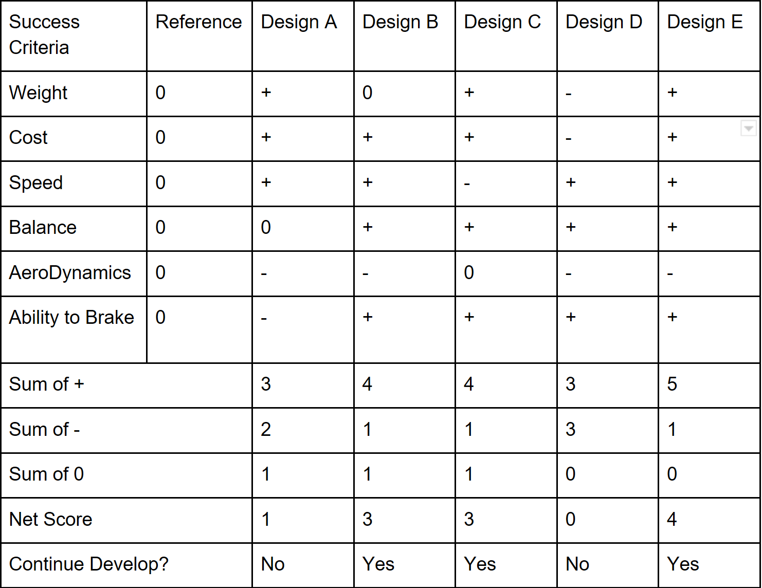
We have chosen to move forward with Design E which is the team design. This had the highest scores in both the concept screening and concept scoring tables. It in theory is very fast and balanced while staying at a low cost. The only foreseeable downside is how the two motors will react with one another. We have also decided to continue researching Design C because the servo may be able to cut costs while keeping the design efficient and light. The downside could be if the servo turns too slow it could affect the ability for the design to do its objective in a manageable time.
Moving Forward into AR&D
Planning
- Motor Configuration
- Wind Tunnel
- Two motors back to back mounted on a custom offset