Approach/Vision
The vision of Team P is to have a working AEV for our intended audience for under the maximum budget. Our intended audience includes people in need of transportation that is inexpensive, reliable, safe, and environmentally friendly. Our plan/approach to design is to develop a lightweight AEV that is durable and has consistency in performance. In order to achieve this through the vigorous process of designing and redesigning the AEV through testing, the team will focus on creating a good design relatively quickly, then to focus on refining code for optimal performance. We are developing a vehicle that would transport cargo with reliability, safety, speed, and cost/environmentally efficient.
Backward Looking Summary
Situation:
(Since the last progress report) Division P has chosen the desired chassis, analyzed energy output, and resolved hardware problems.
Division P has finished designing all of its AEVs and has chosen a new chassis. This chassis (Figure 1) has yet to be used and weighed. The original AEV had a mass of 265 g, but Division P believed the new chassis would cut down on the mass substantially. With a less massive body, there would be a smaller force necessary to overcome the friction between the track and the wheels of the AEV.
The first task Division P had worked to accomplish is the analysation of the energy output and performance of the sample AEV. To do this, Division P has been running the same code on a single track and recording the energy output of the motors and measuring the distance travelled by the AEV. For the tests, The division tested both the given AEV and a modified AEV that had a mass of 251g. Due to complication with the reflectance sensors, the division was unable to collect meaningful data for most runs. Once the reflectance sensors were replaced, Division P collected the data for the modified given AEV.
Results:
While using the same code as all previous runs, Division P found that the more massive AEV drifted to a final distance of 3.01 meters (Figure 1). The less massive AEV drifted to a final distance of 3.20 meters (Figure 2). Given that both of the tests were performed using the exact same code, therefore the same amount of energy, Division P concluded that the less massive AEV was more energy efficient.
Tables/Figures:
Figure 1) Tests with more massive AEV (265g)

Figure 2) Test with less massive AEV (251g)

Takeaways:
The takeaways that Division P gathered thus far are that mass effects energy output and that the reflectance sensors need to be facing the same way. Energy optimization was found to be done with lower masses. The data shows that generally an increase in mass results in a decrease in distance travelled, this was expected because it increases the friction between the rail and the AEV. Reflectance sensors need to be connected with the black wire to the ground, otherwise data recovered will be skewed.
Looking Forward Summary
Division P’s next focus is the development and testing of the newly fitted AEV chassis that was 3d printed as well as the writing of the code that will make the AEV perform it’s desired task. Testing the AEV will decide whether the new chassis meets the divisions standards for weight, safety, and energy efficiency. This design at the moment fails to encompass all of the required materials, as it cannot support a magnet mount far enough away from the arduino. This will be the primary tasks for team P’s R&D team, to redesign the chassis to support a mounting point. The other task that is primary focus is writing code that will be used in during testing. The software design team will be handling this task. These two tasks should be completed within the next three weeks, this allocates enough time for a multitude of testing and re-evaluation of past results and results from new testing.
Upcoming goals:
- Establish the final design for the AEV and send out for 3d printing/ laser cutting
- Write testing code and start working on final code development
- Decide on two or one motors, influences designs and choices made while coding
- Run performance tests and AR&D 2 over track variance and determine how that affects final coding
- Update website and keep detail notes about tasks performed and changes that were decided upon by team
- Collate data and determine which data is useful or valid.
Upcoming schedule
1 Week needed –
- Determine the final design for the AEV. This will be accomplished by the whole team but will be headed by Shepherd Gruver. To accomplish this task only 1 week will be designated as it is very important to do this before accomplishing other related tasks. No materials will be need other than the 3d printing equipment. At this point it will be his sole decision but should be influenced by the other members of the team for major design changes. Two hours will be allocated for the redesign as it is imperative that it is sent out soon.
- Decide on two or one motors, influences designs and choices made while coding. This will be accomplished by the whole team but final decisions regarding code will be Jeff Morhous and Coltin Thomas. Only 1 week will be designated to this, it will be decided somewhere during testing due to the practical nature of redesign during the challenge. Each team member is required to fully understand how to program and read the programming that is developed. 1 hour of lab time is allocated to this decision so that the design team can advance in their work.
2 weeks needed-
- Collation of Data and further testing. This has been allocated two weeks or 6 hours of class time so that proper testing may take place and data can have proper analysis to help in our determinations for design and coding choices. The whole team will work on this but people will be specialized to specific tasks so that the process becomes easier.
| Task | Teammates | Start Date | End Date | Time Needed |
| Final Design | SG | 3/19/2017 | 3/26/17 | 2 hr |
| 1 vs 2 motor | All | 3/21/2017 | 3/28/17 | 1 hr |
| Collation and Collection of Data | All | 3/26/2017 | 4/9/17 | 6 hr |
Here is a glossary of the basic Arduino functions that will be used in our codes.
- celerate(m,p1,p2,t); Commanded the wheels to accelerate or decelerate. Identified the motors that will react (m), the percent power at the beginning and end (p1,p2), and the time period (t) in which it will accelerate/decelerate.
- motorSpeed(m,p); Sets a motor (m), to a power percentage (p).
- goFor(t); Indicated how long (t) the motor will run at its current level.
- reverse(m); Reverses the direction of motor (m).
- break(m); Commands motor (m) to stop spinning.
- reverse(m); Reverse the polarity of motor (m)
- goToRelativePosition(n); Commands the vehicle to move a number (n) of marks from the current position (can be negative or positive)
- goToAbsolutePosition(n); Commands the vehicle to move to a location a certain number (n) of marks relative to the position from which the AEV originally started
Evolution of Design
To begin the design process, our team decided to use the sample AEV design that was provided to us by Engineering 1182 faculty.

While this design is adequate, the team strove to improve in all ways possible. Given a basis for the design, each team member sketched orthographic views of proposed new designs.
(Drake’s Sketch)
The main goal of this design was to reduce weight and reduce drag. Reducing both of these factors would improve the top speed of the AEV, but more importantly, it would reduce the power needed to run its route. The longer thin base allows for there to be enough area for the controlling units while minimizing unnecessary weight. The intent of the front is to reduce the drag force and redirect air towards the propellers.
(Jeff’s Sketch)

The intent of this design was to minimize the space that the body took to house the Arduino board and the battery. In doing this, I hoped to save on the overall weight of the AEV and consequently increase power efficiency and even time to run. The shape concept of this design was modeled after a boat in order to allow for maximum stability in hanging from the track. The front is sloped to increase aerodynamics. However, the designed seems excessively wide to reach its intended effect, which leaves much to be desired. The team hopes to improve on this design and combine ideas from the other to make a final AEV design that meets the overall team goals.
(Coltin’s Sketch)
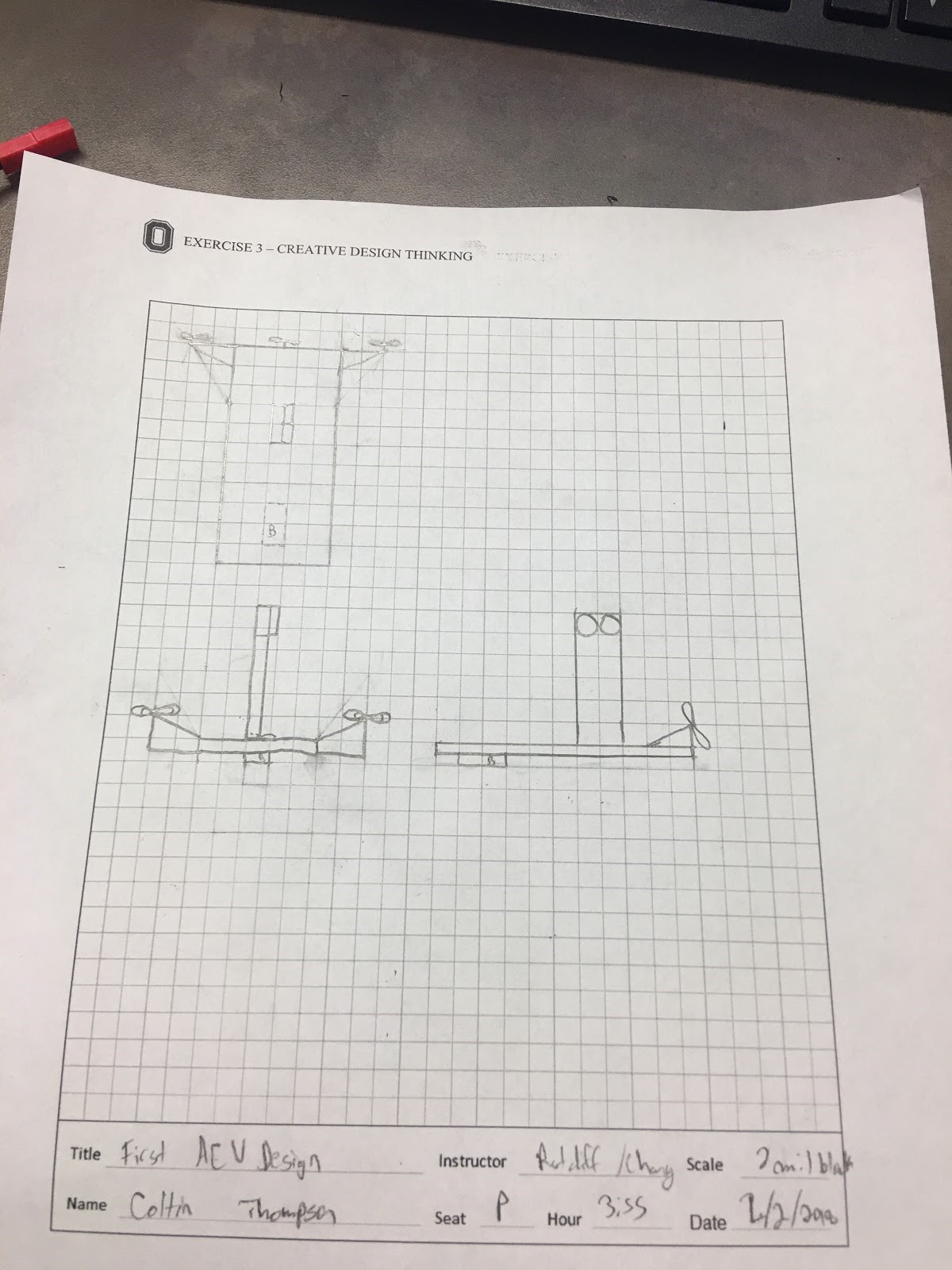
The main goal of this design was to be the bare minimum, light, and aerodynamic. The battery is in the front to act as a counterweight to balance the AEV as a whole. The propellers are meant to have 3 blades in order to maximize efficiency and lower energy consumption. This would minimize weight and maximize the energy performance through what we learned last semester using a wind tunnel.
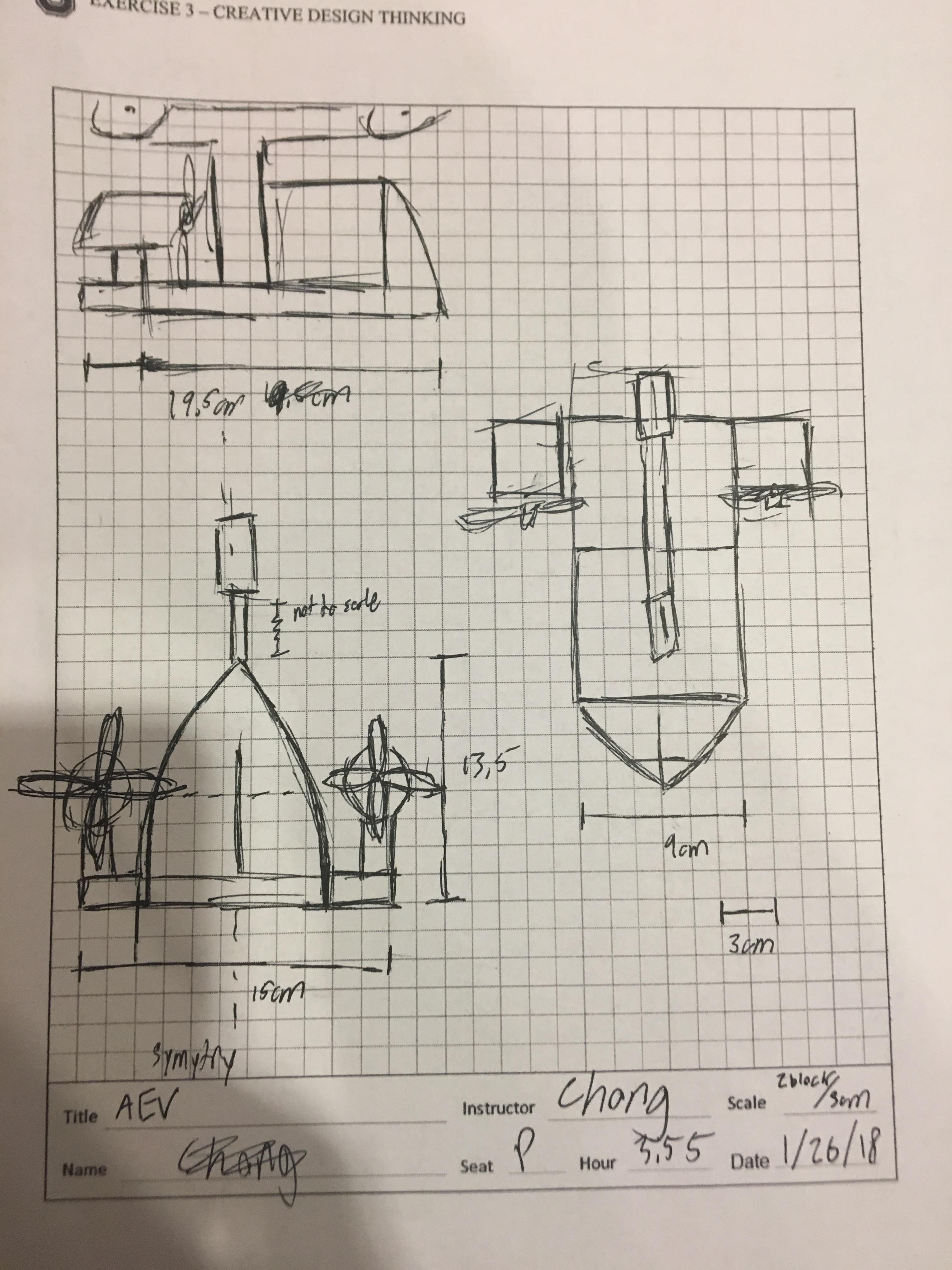
(Shepherd’s Sketch)

The main goal of this design was to be the bare minimum, light, and aerodynamic. The design is made in a way that it keeps the center of gravity towards the rail that it stays on, and to keep mass and aerodynamic drag as low as possible.
Each proposed design offers improvements on the original design to meet the team’s vision of efficiency, affordability, safety, and reliability.
Advanced R&D
Current AEV design –

Sideview for the current plan:

This design is a composite of the team’s ideas and goals for the AEV, it will likely evolve as we seek to minimize the mass of the AEV chassis.
Energy Analysis:
The following Arduino Code was used to test the AEV during lab 5

After the run was executed, this graph of Power vs. Distance was generated
2/26/2018
Our division has modified the given AEV in order to test the effects of reduced mass. Additionally, we had our modeled chassis 3D printed.

(left to right: Our 3D printed chassis, the modified AEV to have a lower mass.)
The modified AEV has a mass approximately 15 less than that of the original given AEV. The designed AEV has a mass less than 11 grams. We expect to see significant improvements in efficiency with our new chassis.