Posts

AEV // Lab 6 Progress Report

The Purpose for this lab is twofold, to generate and test a way for gathering the information collected by the AEV and to better understand how the AEV functions on the test runs. In order to complete this lab, both parts were tacked separately, with some working on the AEV and its Arduino code and some working on how to interpret and graph the data collected with MATLAB code. This lab took place over multiple days, and the not all of the data could be collected together, as the EXCEL spreadsheets given by the AEV were not collected for the second part of the lab, but the code for the AEV to run in the second part of the lab. 

Below are the results for the half-track runs.

Figure 1. Watts vs. Distance for flat run 1 

Figure 2. Diagram of the watts vs. time for flat run 1 

Table 1. Phase Breakdown for flat run 1

The flat track run 1 went well but by the data generated for half-track 2 was lost and could not be included in the lab report. As such, conclusions will be drawn from the first half track run alone. The flat track that was tested was coded simply but was enlightening when it came to a couple of concepts. Unsurprisingly, the part of the run that was the required the least amount of energy was the one that had the AEV not running it’s propellers, but what was surprising was the fact that the energy that it consumed was not zero. The other aspect that was interesting to note was how the third phase of the test took less energy than the first aspect. This part was shorter, however when looking at the Watts vs. Time graph it is apparent that even as a whole the entire thing required less power to operate even with the motors set to the same speed. This will make it so that the team will do two things in the future. When it is possible to have the motors not running, have them turned off, but have the AEV at a standstill for as little as possible. 

Below are the results from the half-track runs.

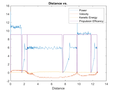
Figure 3. Compressed plot of the half-track data

Figure 4. Plot of the power versus time

Table 2. Phase breakdown for the half-track run 

For the half-track run, there was not much information that was used from the flat runs that was carried into the new run. The group members that worked on the flat track were not the same that worked on the half-track run, so there was little crossover. The interesting thing to note from this run, is how power is saved when the motors stop running yet the AEV keeps moving. 

The issues that were encountered during the testing phase were slight for the flat track runs, but for the half-track runs the main issues were getting within the correct test parameters. The code had to be tweaked, then run, then tweaked again to get the test to complete correctly which took a fair amount of time to complete. 

AEV // Lab 5 Progress Report

The purpose of this lab was to measure the thrust of the propulsion system using a wind tunnel; in this the velocity of the wind tunnel was controlled and various data readings were acquired. From this acquired data, the efficiency of the propulsion system was determined by setting the input power to the motor and measuring the power output. For this lab, a tractor (or puller) propulsion system was measured, and data was gathered. After the lab, the data was put into another table, and additional values were calculated, such as the Propulsion Efficiency and the Propeller Advance Ratio. The analysis was then considered, and ideas were conceived on how best to implement fans into the AEV that will be designed in the future.

Table 1. Data gathered by the group

The data gathered was incorrect. For the correct readings given in the excel spreadsheet, the Thrust Scale readings always went up, yet the recorded readings decreased with each run. The measurement error was incredibly high and rendered the table below basically unusable. Conclusions reached will rely on data provided in the excel sheet.

Table 2. Data analysis from the group 

As stated earlier, the data here is extremely unreliable. For the numbers to make any kind of sense at all the thrust calibration datapoint had to have its absolute value taken, as negative numbers are impossible to exist in a physical environment for items such as the propulsion efficacy.

Figure 1. Propulsion Efficiency vs. Advance Ratio for all fan designs 

From this figure, the maximum efficiency for each fan design, with both pushing and pulling settings can be found. Visually, it is apparent that the EF-3 bladed design in pull mode has the overall highest efficiency with an advance ratio of around .6 and below, which corresponds to the AEV power of over 20%. The other possible efficient design, especially at low speeds, would be the EP 3030 design at 27% or lower.

Figure 2. Thrust vs. Power for all fan designs 

The figure states which fan creates the most thrust at the Arduino power setting. From this graphic standpoint, it is obvious that the most thrust that a blade can achieve, out of the blades tested on the push or pull setting, is the EF-3 bladed design. It outperformed the five other blade designs in this analysis section. This lab will aid the design of the AEV in the future by influencing what propeller will be included in the design of the future AEV’s. Looking at the figures above, it is obvious that one of the favored designs that will be considered is the EF-3 pull design, and the EP-3030 design, as both of these scored highly when considering how efficiently they can run compared to the other fan designs. Whether or not that the most efficient way to run the AEV is feasible is a problem to be looked at in another test, but the knowledge of the most efficient blade design/motor speed combo will be important for the optimizations made in the future. The differences between pushing and pulling configurations are important because they reflect the different performances that can be expected with an AEV with front and rear facing propellers. Despite the performance differences between the two configurations, there are many design possibilities where both could be a major design strength, but it is important to understand the efficiencies of the configuration before including it into a design. Testing in a wind tunnel is a less time-consuming method of discovering the potential weaknesses of a design decision and is extraordinarily useful when considering where to put the propellers.
With the data that was gathered, the most efficient way to have the EF-3 design would be at 50% power for the pushing and pulling efficiencies.


AEV // Lab 4 Progress Report

The purpose of the lab was to better understand and implement the external sensors into the design of the AEV. For this lab, the two external sensors were suppled along with a way to tie them into the arm of the AEV that attaches to the monorail. The sensors were placed into the arm of the AEV and screwed in, then attached to the Arduino board of the AEV. In the first part of the lab, the sensors were tested with the reflectanceSensorTest(); command, with the first run revealing that the sensors were placed in backwards. This was quickly fixed, with the sensors found to work perfectly well. After the sensors were successfully tested, an Arduino program was coded and then uploaded to the AEV. This was then tested on the monorail track and immediately found that a reverse() command was needed at the beginning of the code, as the AEV ran backwards. The command was implemented into the code, and the test was then completed successfully.
After the Arduino was programmed and placed on the track, it moves slowly forward and reverses quickly backwards. It moved forward 10ft and 8ft backwards. For this lab the AEV did survive this trip and had a well-maintained center of gravity throughout the duration of this trip. The AEV design is satisfactory as no issues were encountered while the test was being run. Like mentioned in the introduction, only minor errors were encountered like the sensors being placed backwards and a lack of the reverse() command but those were fixed before being placed on the track for its run.
The commands that will be used to code the AEV will be the goToRelativePosition() command and the motorSpeed() commands, as those will add consistency to the functionality of the AEV. Other commands will be used, but the two listed above remove the inconsistency of the goFor() command, as the goToRelativePosition() command will allow the AEV to go to specific points on the monorail instead of relying on allocated time in the goFor() command to create the correct distance. motorSpeed() is a useful command as it allows the AEV to be controlled in a direct way. The goToRelativePosition() command heavily uses the sensors which appeared to work well.
The MCR states that energy management, operational consistency, and operational efficiency are key to the AEV project. The goToRelativePosition() command allows the user to direct the AEV’s position in a consistent manner in relation to its current position as it uses sensors to finely track movement. The gotoAbsolutePosition() command functions in a similar manner, but moves the AEV in relation to a fixed starting point. This is particularly useful for directing the AEV to fixed positions along the track. The command motorSpeed() controls the percentage of power supplied to the motors, which may be tuned to find the most efficient use of power to reach the desired destination.
The first problem that was encountered in the lab was the correct way to connect the sensors to the AEV, as the orientation of the wire that connected the two was oriented in the wrong way. This problem was quickly overcome, as the orientation was quickly corrected. The second issue that was encountered was that the sensors themselves were connected backwards, as the sensor test revealed that the AEV wheel registered that they were going backwards when they were going forward. This problem was overcome when the sensor connection to the AEV was reversed. The final problem was that the reverse() command that is in the final code was left out initially, causing the AEV to initially travel backwards. All that was required to fix this issue was the insertion of the reverse() command (See figure 1).

Figure 1. The Arduino Code

AEV // Lab 3 Executive Summary

The purpose of this lab was to conceive and implement both a screening and scoring matrix to critique and improve current and future AEV designs. The lab was completed in two ways, with the matrices being built and the AEV being test run on the monorail for the first time. To complete the first part of the lab, the AEV was assembled to the reference design. After this was done, an Arduino code was created by referencing a sample given by the lab. This code was pushed to the AEV and it was tested on the monorail. The design was tested on the monorail twice, with the second test being much more effective than the first. The second part of the lab was focused on the creation of scoring and screening matrices. To create the matrices, the lab manual was referenced and combined with qualities believed to be beneficial to create the tables. For the scoring matrix, weighted values were assigned based upon the believed relevance. The tables were then completed, with the strengths of the designs being highlighted.

The concept screening and the scoring spreadsheets are designed to help compared the sample AEV model to the three AEV designed concepts created by the team in lab one. These spreadsheet had criteria choices such as balance, center-of-gravity, durability, cost and environmental. Each of these are important as it relates to an AEV concept to be used by a state park. The balance and center-of-gravity criteria goes together as you want the AEV concept to be well balanced, as well as it being able to find its way back to the center after being blown from side to side by the wind and/or other weather elements. The durability of the AEV is important as it’s important that the design can withstand the elements. As for cost, it should take into account the elements the AEV would endure, as well as how frequently it would be used for tourists. Lastly, in relation to its environmental aspect, it should be durable but not affect the landscape surrounding it too much in way that would cause it could sustain future damage from the elements.

The monorail design is the most favorable design when looking at all the criteria. One of its main features is its well roundedness in comparison to the other designs. The design seems that it would work well when placed on a monorail, as it has both good balance and center of gravity, as the design slants inwards, causing the material to balance itself within the passenger or cargo hold. Another major strength of the design would be the its cost, as it only uses simple materials that would be inexpensive to produce and to assemble. Maneuverability is another plus, as it would be able to turn well along the monorail. One of its major downsides, however, would be that it would be less durable, considering that the wings are of considerable mass attached at an angle. The environmental impact might also be considered. The Bus was the least exceptional design. Its pros would be that it has a clear center of gravity, and a low environmental impact as it has a small footprint that would require less resources to
move. Its downsides would be that it would be less maneuverable due to its wide wheelbase and its durability considering its smaller size. The train had a projected performance between the monorail and bus but seems to be much better than the bus design. Its major benefits include its excellent balance and center of gravity, countered by a high projected price and potentially higher environmental impact.

If the park management would approve it, the monorail design would be the one that would be carried forward as a base for improvement. It is exceptionally well balanced with no considerable downside, and this well roundedness would allow it as an excellent base to create and test other designs on top of. The major benefits of the other designs would be incorporated as well, but the monorail base did outscore the other designs on the scoring matrix.

Table 1. Concept Scoring Matrix 

Table 2. Concept Screening Matrix

Figure 1. The Code Executed During Lab 3

To improve on the monorail design, tests must be performed to more accurately determine component piece placement in order to distribute weight in a balanced way. Further testing may be conducted to determine optimal “wing” placement, which also determines motor placement. The challenge is to maximize AEV efficiency and cargo capability while maintaining a durability.

The first trial on the track revealed a lean to one side, which demonstrated an inefficiency to the design due to a decrease in horizontal displacement compared to if it had been balanced. In the second trial, the AEV was altered to be balanced and the results showed a significant increase in performance. When the code was activated, the AEV moved after a brief pause as the motors were brought up to a speed significant enough to push the vehicle.

The track trials stressed the importance of balance for the AEV in order to get best performance from both motors provided that the motors are symmetrically mounted. In order to balance the AEV for the second trial the arm containing the wheels was moved off the center axis, which proved to be an adequate fix. Further designs may incorporate this adjustment while maintaining symmetry in all other aspects. At 25% speed the motors provided significant thrust to warrant seizing the AEV before it entered unauthorized sections of the track. Future code will require additional trials to determine appropriate values

AEV // Lab 2 Exceutive Summary

The objective of this lab was to develop basic understanding of how to program in the Arduino IDE and how to push programs developed on it to the AEV. To accomplish this, the AEV was taken out and assembled in the same manner as was in the last lab, the only difference being the battery which was charged and utilized during the lab. The Arduino IDE was also installed on multiple personal computers, with tasks being completed in parallel in order to give all group members experience with the programming aspect of Arduino. Scenario one was completed successfully with the AEV completing the program laid out for it within the lab time. Scenario two, however, was not completed within the time allotted for the lab. In scenario one, line one, there was resistance observed in the motor to rotate the propeller at low speed; with the Arduino we were not to exceed 40% power or else the Arduino would burnout. Exchanging the motor for a different one would not produce different results. The commands in the lab would impact the success of an AEV that may somewhat limit its success as the commands cannot move the entire device precisely. To achieve full control of the AEV, many different commands would need to be used in tandem, instead of having a simple command execute a maneuver perfectly. For example, in order to get the AEV to stop, the brake command cannot be used as that command only stops the propellers from spinning. To get the AEV to come to a full stop, the propeller would be made to spin in the opposite direction and time would need to be allowed for the AEV to slow down. There were not any errors during the lab. Additional instruction to sync the Arduino and computer was requested and resolved. The team was not able to complete the entirety of scenario two, as went spent most of the time on the Arduino coding for scenario one, ensuring that each of the group members understood how it works. We were half-way through scenario two when the lab ended.


Scenario 1 Code:

celerate(1,0,25,2.5); // this command involves setting what motors to run, how fast to accelerate (start-end) and for how long.

motorSpeed(1,25); // this command involves selecting a motor and how fast it should run.

brake(1); // for this, select which motor to brake.

celerate(2,0,27,4);

motorSpeed(2,27);

goFor(2.7); // for this, determine how long the previous commands should run for — it also follows up the motorSpeed command.

celerate(2,15,0,1);

brake(2);

reverse(2); // for this, you select which motor to put into reverse

celerate(4,0,31,2);

motorSpeed(4,35);

goFor(1);

brake(2);

brake(4);

reverse(1);

celerate(1,0,19,2);

MotorSpeed(2,35);

goFor(2);
MotorSpeed(4,19);

goFor(2);

celerate(4,10,9,3);

brake(4);


Scenario 1 was designed to make students familiar with controlling various aspects of the motors. These aspects included: percent power applied, duration, power scaling, braking, independent motor operation, simultaneous motor operation, and reverse operation. Within the first three steps, the first motor was programmed to scale up to 15% power over the course of 2.5 seconds, maintain that power for one second, and then brake. This demonstrates the first four aspects of those mentioned above. Throughout the program, motors were also driven simultaneously, but with different instructions for each, which expands AEV control capabilities in further projects.

While not performed, Scenario 2 was a “fun” code that demonstrated the ability to make “music” from the motors to the tune of The Imperial March from Star Wars.

AEV // Lab 1 memo

Bus Sketch // Initial Design

This design was based off something reminiscent of a formula one car. The body was low to the ground and the tires were wider than the body of the car for stability. The design uses the electric motors and propellers at the back of the design to power the bus, with the passengers seated along the spine of the design, seated behind a windshield that would make the ride more comfortable for those riding. The battery and the control unit would be seated at the back of the design to balance the weight from the front of the bus, and the design could be extended lengthwise in order to fit more passengers. Overall the design prioritizes the balance of the AEV, as tipping over seemed to be one of the greatest concerns for a ground-based vehicle. The downsides to this vehicle would be its low speed and its lower capacity to fit passengers. Seeing how this design is smaller than other similar types of AEV’s it follows that there would be less passenger capacity. Likewise, due to the priority on passenger safety, the speed of the machine would be low.

The considerations that must be made for a ground AEV are mainly since there is no premade rail for it to ride along. Of course, wheels must be used along the ground for the vehicle can function, and balance must be accounted for as the vehicle must stand on its own. The vehicle must also account for uneven terrain or an incline or decline in the road. Like all AEV’s the design must also consider how it will move, and what will power that movement. The design must account for the passengers that will be seated in the AEV, and how they will be protected from the elements such as the wind or rain. These design elements are also present in all other AEV designs.

Monorail Sketch // Inital Design 3

The inspiration of this design is based off paper airplanes, as well as the sample AEV model from class. It is a simple design in itself; this is so that with the addition of cargo or passengers, the maximum weight requirement isn’t met. The design has panels slanted upwards on each side and has a half V-shaped attachment at both the front and the back, the idea is that this will help the monorail design be more aerodynamically fluid. The cargo and/or people, will be placed in between the automatic control system and the rail hook with the wheel attached, placing them here allow for an even weight distribution and safety for passengers and cargo. There is an option to ride behind the rail hook with the wheels attached but it is far less safe because it is an open design at the back near the propellers. It must be said that this design is not drawn to scale and is subject to change depending on where the monorail is meant to be implemented.

Train Sketch // Initial Design 2

The “train” concept is designed to ride on top of a single, T-shaped and grip onto it from the bottom. This allows the train to remain securely on the rail without fear of instability or tipping despite speed or weather conditions, provided that the rail itself withstands the stresses places upon it. The platform to be used for passengers and/or cargo is attached to the rail clamps via vertical, rotating shafts to allow for tighter turns than a fixed fastening point otherwise would allow. The design uses direct drive as the method drive the vehicle, which eliminates the need for additional components to control speed when going downhill and has direct energy transfer from wheel to rail. Finally, the vehicle has a fairing to provide increased aerodynamic smoothness and comfort to passengers when travelling at various speeds. The values for width, length, and weight are subject to various criteria, to include the environment at which this is to be implemented and are subject to change


The first lab consisted of developing three different AEV designs, one of them consisting of a monorail design (initial design 3). With each design, is a description that states the strengths of this design but also the weakness of it. The three designs were ranked on a 1 to 3; 1 being low, 2 being moderate, and 3 being high.

The Bus design has a low user comfort, a moderate energy consumption and high energy available.

The Train design has high user comfort, a low energy consumption and low energy availability.

The Monorail has a moderate user comfort, a high energy consumption and low energy availability.