Three main areas were researched throughout the project of the AEV. The goal of conducting research was to help improve the AEV by making it faster, lighter, and more efficient. The three areas of research can be see below.
Weight Distribution
It was first observed that the AEV was not well balanced early on in the project. While sitting on the track, the AEV would tend to lean forward or to the side. This could reduce the efficiency of the run so it was decided that it needed to be fixed. The weight distribution was test by setting up multiple configurations of the ‘L’ and ‘T’ crossbar on the AEV. Each configuration was placed on the track and it was observed to see how the AEV sat. In addition to the crossbar, different parts of the AEV were also tampered with to see if they would cause excessive tilting of the AEV. It was concluded that the most important factor with the weight distribution was having the wheels centered with the center of mass of the AEV. Having the wheels in line with the center of mass greatly reduced the tilt of the AEV. Also, the position of the other components of the AEV does matter. Having the other components with the center of mass was also crucial to the weight distribution. Lastly, it was decided to use the T crossbar instead of the L crossbar. This would ensure the weight of the AEV is evenly distributed across the track.
Propellers
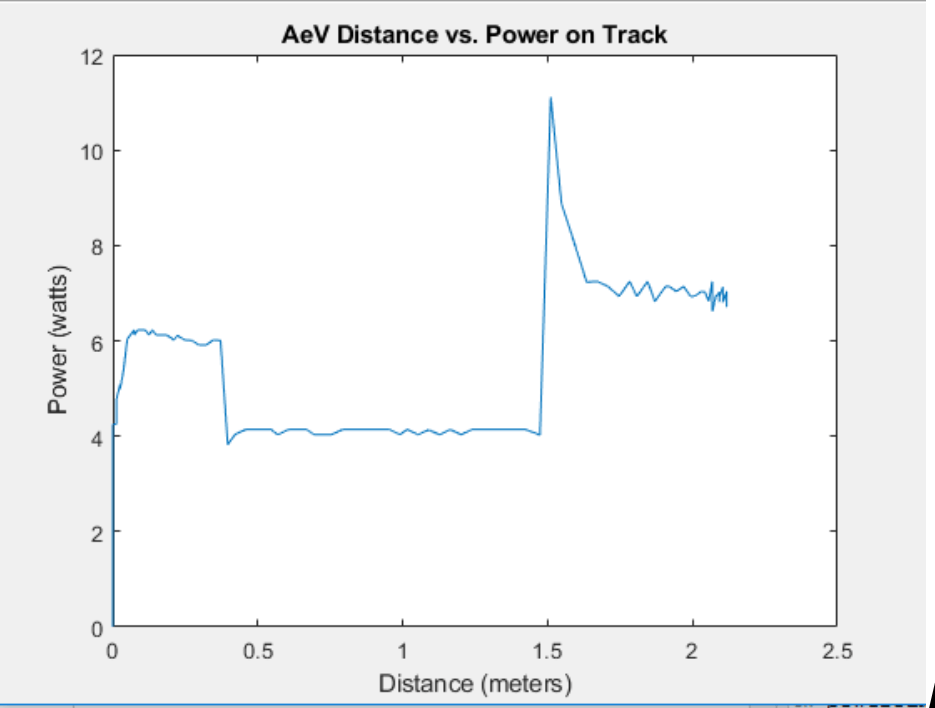
The second area of research conducted dealt with propeller configurations. Two different types of propellers were given to each group, so the group wanted to see how big of an influence each propeller had on the speed and power of the AEV. Each configuration would be tested with the same code and then analyzed after. The first propeller test was a flat, rectangular propeller. This flat propeller was immediately ruled out because there was no movement of the AEV. The propeller did not create enough airflow to move the AEV anywhere. Next, the curved air foil propeller was tested. It was observed that the airflow propeller created enough airflow to move the AEV across the track. Therefore, it was obvious to see which propeller needed to be used. One last test was conducted on the air foil propeller. The group wanted to see if the speed and power changed at all if two propellers were placed on each motor instead of one. Like before, the same code was used and then compared for each run. After analyzing the data, it was seen that the double propeller configuration did move farther and faster than the single propeller configuration. However, the double propeller configuration did use more power, which was not the most ideal. So in the end, the single propeller configuration was chosen to be implemented into the final design, mainly because it was more energy efficient. Below are the graphs from each propeller configuration.
Single Airfoil Propeller Setup

Double Airfoil Propeller Setup
Single Rectangular Propeller Setup

Servo Motor
The third and final research conducted was on on the servo motor. The servo is a mini motor with an arm attachment that could rotate up to 180 degrees. The goal of this research was to find an efficient and appealing way of implementing the servo as the AEV’s new braking system. Before the research, the AEV would brake by reversing the propellers. However, reversing the propellers to slow the AEV down required a lot of power and the stopping point for each run was inconsistent. The servo would hopefully solve this problem. To understand how the servo worked, the group first tested the servo on a small stationary track. A zip tie was used to attach the servo to the T crossbar and then a code consisted of only rotating the arm was uploaded to the AEV. After the desired angle was found where the arm rotated against the track, the servo was tested on the actual track with a code that had the AEV actually moving. It was observed that this braking system worked. However, the servo arm needed to be slightly longer and the group needed to find a better way to more securely attach the servo to the crossbar. These problems were fixed by using rubber bands around the servo to attach it and putting a pencil grippy with duct tape on the side over the arm of the servo. This would make the arm long enough to easily reach the track. Below are two energy graphs: one with the servo braking system and one with the propeller braking system. It can be seen that the servo used much less power to brake the AEV.
Servo Motor Braking System

Propeller Braking System
