Exercise 1 – Programming Basics
The team explored various Arduino function calls by programming the AEV’s motors to run through multiple different scenarios with varying motor speeds and braking. While running each scenario, it was observed that there was resistance in the motor to rotate the propeller. It did not begin to rotate at the start of the program.
Exercise 2 – External Sensors
The team tested the AEV’s external sensors using a similar approach to “Programming Basics”. The AEV was ran through a programmed scenario on the track to test the function of the external sensors and make observations of certain functions such as reverse and brake. It was observed that using reverse and brake as a method of stopping the AEV was not precise. The reflectance sensors are crucial to the completion of the MCR. The sensors count rotations of the wheel and will allow the team to program the AEV to travel to specific distances.
Exercise 3 – Creative Design Thinking
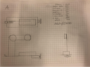
Individually, each team member drafted an orthographic sketch depicting what they thought was the best design for the AEV. As a group, a concept sketch of the AEV was also drafted. The MCR was taken into account with every draft sketch.
Design A (Figure 2 above) features a lightweight and efficient design in order to meet the budget constraints of the MCR. It would be successful in completing the scenario due to its low cost for development
Design B (Figure 3 above) is a powerful but light design that aims to carry slightly more passengers than design A. It would be successful in completing the scenario because of its powerful propellers and light design.
Design C (Figure 4 above) is a heavy but powerful design with the purpose of carrying more passengers. It would be successful in completing the scenario because it will allow more passengers to utilize the vehicle.
Design D (Figure 5 above) is an efficient, aerosynamic design. It would be successful in completing the scenario because of its efficiency in traveling through the air which reduces power requirements.
Design E (Figure 6 above) is an aerodynamic and efficient AEV design which is appealing to passengers. It would be successful in completing the scenario due to the aerodynamics of the design as well as the efficiency. It would not require as much power for each run. Also, if passengers like the look of the design, they would be more inclined to use the transportation system.
Exercise 4 – Design Analysis Tool
The team explored a design analysis tool that would allow evaluation of AEV performance. The program communicates with the Arduino motor controller and provides statistics from AEV test runs. The AEV Analysis tool was installed via MATLAB and calibrated. The team ran the AEV through a scenario on the straight track to collect data. (Code can be found here. Refer to “Exercise 4 Arduino Code (CSS1)”).
In Figure 7 (shown above), from 0.00 to 3.00 seconds, the AEV was accelerating all motors from 0-25%. From 3.00 to 4.00 seconds, the AEV’s motors were set at the constant speed of 25% power. From 4.00 to 6.00 seconds, the AEV’s motors were set at 20% power. From 6.00 to 8.00 seconds, the motors were reversed and ran at a constant speed of 25% power. After 8.00 seconds, all motors were braked.
In Figure 8 (shown above), the initial climb is the motors overcoming resistance before spinning. The first plateau in the graph is the result of running the motor at 25% power for one second. The second plateau is the result of running the motors at 20% power for two seconds. The tall spike in power supplied and lack of distance traveled is due to reversing the motors. The plateau after the spike was caused by running the motors at a constant speed of 25% power for 2 seconds. The loss of power was caused by the brake command and the distance traveled afterward was due to the AEV coasting.
Exercise 5 – Concept Screening & Scoring
Exercise 5 tasked the team with finalizing concepts for the AEV. This was done through design decision-making techniques such as concept screening and concept scoring. Matrixes for each technique were created and the team narrowed down which concepts to further develop.
Table 1: Concept Screening Matrix

In Table 1 (above), the team decided that success criteria for the AEV was aerodynamics, low weight, low material cost, power (motor power), and high efficiency. The best design out of these requirements was Design A which would be continued. Designs B, C, and D are going to be combined into a single AEV concept to continue development.
Table 2: Concept Scoring Matrix
In Table 2 (above), the team scored each category based on a weighted percentage. Again, Design A was determined to be the best and Designs B, C, and D were combined. The Reference Design and Design E was discontinued.
The Reference Design was determined to be average in all categories, so it would be discontinued. Design A was proficient in weight reduction and material cost. Designs B, C, and D were only proficient in motor power. Design E was not proficient in any category so it was discontinued.


