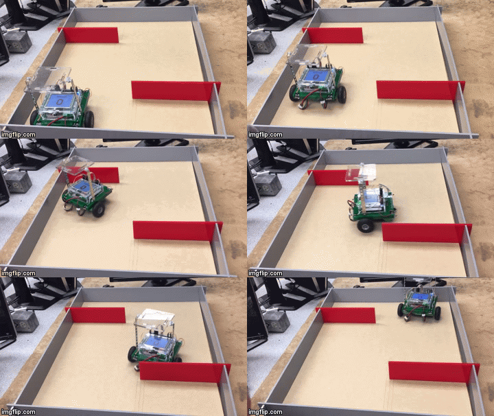
Explorations were laboratory studies that were conducted to assist the team in understanding different means of navigation. There were three explorations, which included studies of motors, sensors, line following, shaft encoding, RPS, and data logging. Each exploration occurred during class time with the help of the FEH staff. All of the explorations occurred within the first few weeks of the design project in order to provide the team enough time to implement what they had learned in the robot’s final design.
Exploration 1: Sensors & Motors
Exploration 1 tested bump switches and the CDS Cell. The CSD Cell was used to read light colors with and without a filter. This allowed the team to understand how different lights will have different outputs, and it helped the team to understand how to read the starting light. When testing the bump switches, the team had to make the robot navigate a simple course with two walls (shown below). When the bump switch was pressed the robot changed directions until another switch was pressed. Having learned how to use the bump switches, the team was then able to use them to let the robot know when it had run into an obstacle. This was used by having the robot align it self on walls as an early form of navigation.
Click to view Exploration 1 Code
Click to view the provided Exploration 1 Writeup
Exploration 2: Line Following & Shaft Encoding
This exploration used three optosensors and igwan motors. For the line following portion of the exploration, the goal was to follow a curvy line of electrical tape that the FEH staff had created. The optosensor reading values for on the line and off of the line and on the line. If the two outside optosensors read off the line and the middle one read on the line then the robot drove straight. If the left two were off the line, but the right one was on the line the robot turned right. If the the right two were off of the line and the left was on the line then the robot turned left. This was useful for the final robot because the core and the bins had lines in front of them that could be read to keep the robot traveling straight. For the shaft encoding portion of the exploration, the igwan motors were used. They had a built in counting system that allowed the robot to know exactly how far it had traveled. The robot had to travel specific distances at different motor powers for the exploration. The biggest takeaway from the exploration was that at higher motor powers the shaft encoding would be less accurate, due to the need to decelerate.
Click to view Exploration 2 Code
Click to view the provided Exploration 2 Writeup
Exploration 3: RPS & Data Logging
Exploration 3 was the first time that RPS was used. A QR code and a crayola bot were used for the RPS portion of this exploration. The goal was to make the robot travel the exact distances that were desired on the course. To do this, the RPS coordinates were recorded before the run so that the robot, the during the run the robot used the coordinates to check that it had moved the proper distances. RPS was used heavily in the final code of the robot, so this exploration was crucial. The data logging portion of this exploration was conducted using RPS and the team’s micro SD card. The goal was to plot a path of the robot’s movements on a picture of the course. The robot checked position and recorded it through out a timed span, and the robot was picked up and moved around the course. When in the dead zone, the RPS returned values of negative one for both the X and the Y. This was potentially useful in creating a map of the course and knowing exactly where the dead zone was.
Click to view Exploration 3 Code – RPS
Click to view Exploration 3 Code – Data Logging
Click to view the provided Exploration 3 Writeup
Exploration Testing Log:
The testing log is located below. All testing occurred in Hitchcock Room 208. The details of each test was recorded throughout the testing process. The log below includes the testing conducted for the previously described Explorations.

